How to Use Motor Control Board: Examples, Pinouts, and Specs
Introduction
A Motor Control Board is a sophisticated electronic circuit board that facilitates the control of electric motors. It is an essential component in various fields, including robotics, automation, and electric vehicles. The board is designed to manage the speed, direction, and other operational parameters of one or more motors, ensuring precise control for a wide range of applications.
Explore Projects Built with Motor Control Board


Explore Projects Built with Motor Control Board
Common Applications and Use Cases
- Robotics: Controlling the movement of robotic arms, wheels, or actuators.
- Automation Systems: Managing conveyor belts, lifts, or other machinery.
- Electric Vehicles: Regulating the propulsion motors in cars, bikes, or scooters.
- Hobby Projects: Powering and controlling motors in DIY projects or model vehicles.
Technical Specifications
Key Technical Details
- Voltage Range: Typically from 5V to 36V, depending on the model.
- Current Rating: Can vary from a few Amps to several tens of Amps.
- Power Ratings: Dependent on voltage and current specifications.
- Control Interface: PWM, I2C, SPI, or UART, depending on the board.
- Protection Features: Overcurrent, thermal shutdown, and under-voltage lockout.
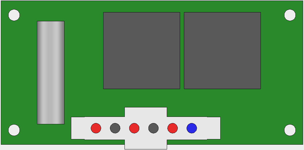
Pin Configuration and Descriptions
| Pin Number | Name | Description |
|---|---|---|
| 1 | Vcc | Power supply input for the motor voltage |
| 2 | GND | Ground connection |
| 3 | IN1 | Input control signal for motor direction |
| 4 | IN2 | Input control signal for motor direction |
| 5 | ENA | Enable pin for motor A, often connected to a PWM signal |
| 6 | OUT1 | Output to motor A terminal |
| 7 | OUT2 | Output to motor A terminal |
| 8 | ENB | Enable pin for motor B (if applicable), also for PWM |
| 9 | IN3 | Input control signal for motor B direction (if applicable) |
| 10 | IN4 | Input control signal for motor B direction (if applicable) |
| 11 | OUT3 | Output to motor B terminal (if applicable) |
| 12 | OUT4 | Output to motor B terminal (if applicable) |
Note: The pin configuration may vary depending on the specific motor control board model.
Usage Instructions
How to Use the Component in a Circuit
- Power Supply Connection: Connect the Vcc pin to the motor power supply and the GND pin to the common ground.
- Motor Connection: Attach the motor terminals to the OUT1 and OUT2 pins for motor A (and OUT3, OUT4 for motor B if applicable).
- Control Signal Connection: Connect the control signals (IN1, IN2 for motor A and IN3, IN4 for motor B) to the output pins of the microcontroller or control system.
- PWM Signal: If speed control is required, connect a PWM signal to the ENA (and ENB) pin(s).
Important Considerations and Best Practices
- Ensure the power supply matches the voltage and current requirements of the motor and control board.
- Use flyback diodes across the motor terminals to protect against voltage spikes.
- Implement proper heat dissipation techniques if the board is expected to handle high currents.
- Avoid running motors at stall current as it can lead to overheating and damage the control board.
Troubleshooting and FAQs
Common Issues Users Might Face
- Motor not running: Check power supply, connections, and signal inputs.
- Overheating: Ensure adequate heat dissipation and check for overloading.
- Erratic motor behavior: Verify PWM signal integrity and connection stability.
Solutions and Tips for Troubleshooting
- Double-check wiring and solder joints for any loose connections or shorts.
- Use a multimeter to verify the presence of control signals and power supply voltage.
- If using PWM, ensure the frequency and duty cycle are within the specifications for the motor control board.
FAQs
Q: Can I control two motors with one motor control board? A: Yes, many motor control boards are designed to control two motors simultaneously.
Q: What is the purpose of the ENA and ENB pins? A: These pins enable the motors and can be used to control motor speed with a PWM signal.
Q: How do I reverse the direction of the motor? A: Change the logic levels of the IN1 and IN2 pins (and IN3, IN4 for the second motor).
Example Code for Arduino UNO
// Define motor control pins
#define IN1 2
#define IN2 3
#define ENA 5 // PWM pin

void setup() {
  // Set motor control pins as outputs
  pinMode(IN1, OUTPUT);
  pinMode(IN2, OUTPUT);
  pinMode(ENA, OUTPUT);
}

void loop() {
  // Set motor direction to forward
  digitalWrite(IN1, HIGH);
  digitalWrite(IN2, LOW);

  // Set motor speed (0-255)
  analogWrite(ENA, 128); // 50% duty cycle for half speed

  delay(2000); // Run for 2 seconds

  // Set motor direction to reverse
  digitalWrite(IN1, LOW);
  digitalWrite(IN2, HIGH);

  delay(2000); // Run in reverse for 2 seconds

  // Stop the motor
  digitalWrite(ENA, LOW);

  delay(1000); // Stop for 1 second before next loop
}
Note: The above code is a simple example to control a motor's direction and speed using an Arduino UNO. Adjust the pin definitions and logic to match your specific motor control board and application requirements.