How to Use RJ45 Socket: Examples, Pinouts, and Specs
Introduction
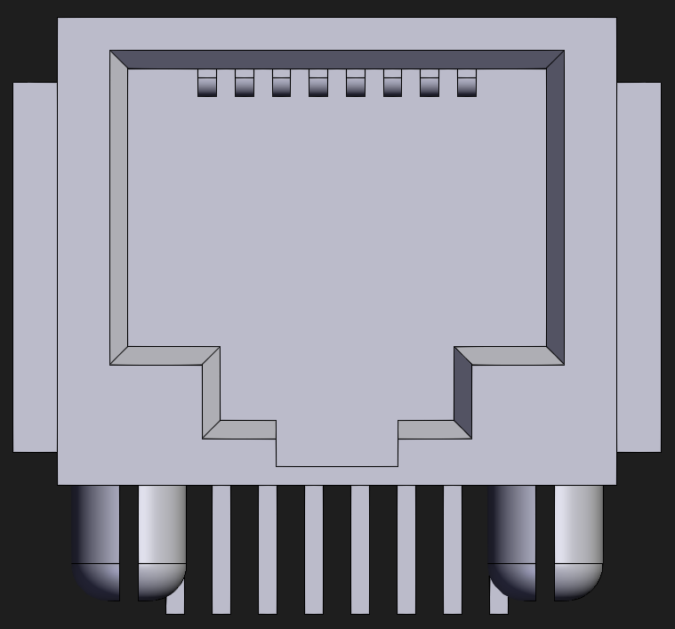
The RJ45 socket is a standardized connector widely used in Ethernet networking. It facilitates the connection of network cables to devices such as computers, routers, switches, and other networking equipment. The RJ45 socket is an 8-position, 8-contact (8P8C) modular connector, designed to support high-speed data transmission in both residential and commercial networking environments.
Explore Projects Built with RJ45 Socket
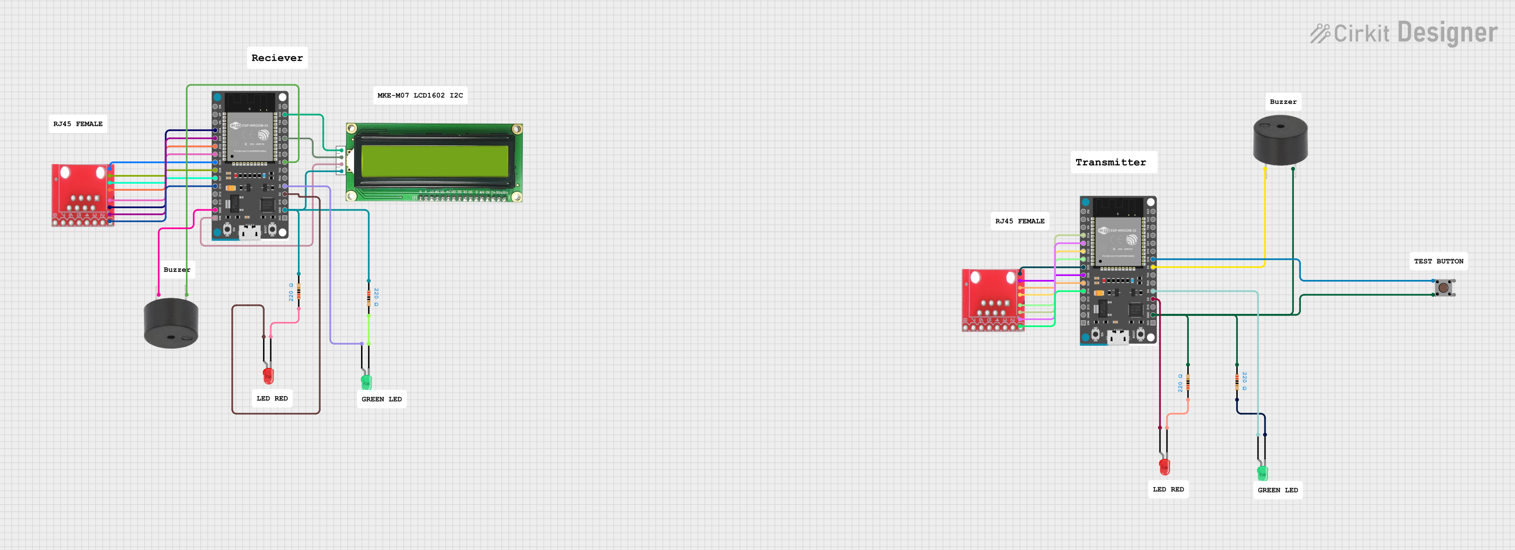


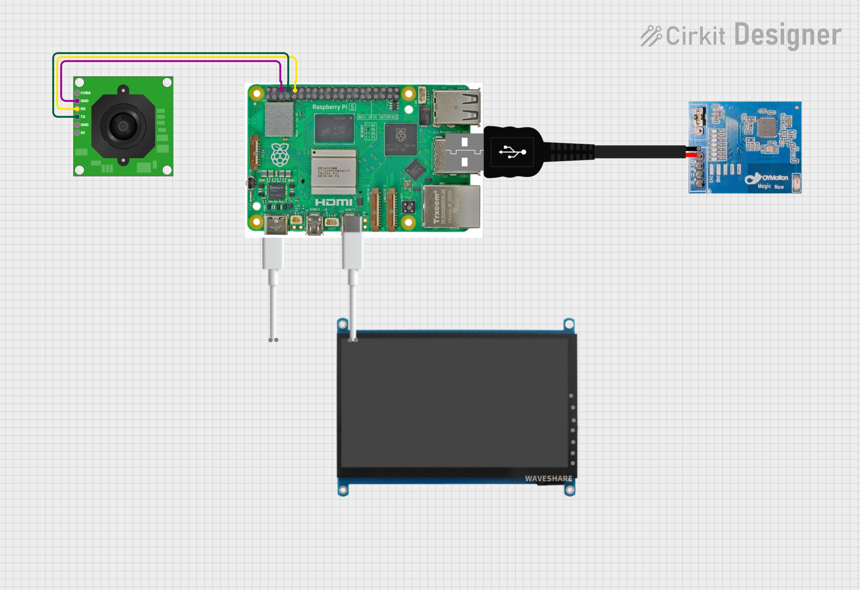
Explore Projects Built with RJ45 Socket
Common Applications and Use Cases
- Ethernet networking for LAN (Local Area Network) connections
- Internet connectivity for computers, routers, and modems
- Industrial networking and automation systems
- VoIP (Voice over IP) telephony systems
- Smart home devices requiring wired network connections
Technical Specifications
Key Technical Details
- Connector Type: 8P8C (8 positions, 8 contacts)
- Supported Standards: Ethernet (10BASE-T, 100BASE-TX, 1000BASE-T)
- Voltage Rating: Typically up to 150V
- Current Rating: Typically up to 1.5A per contact
- Contact Material: Gold-plated contacts for improved conductivity and corrosion resistance
- Operating Temperature: -40°C to +85°C
- Durability: Rated for 750-1000 mating cycles
Pin Configuration and Descriptions
The RJ45 socket uses an 8-pin configuration. The pinout follows the T568A or T568B wiring standards, commonly used in Ethernet cables. Below is the pin configuration for the T568B standard:
| Pin Number | Signal | Description |
|---|---|---|
| 1 | TX+ (Transmit +) | Positive data transmission signal |
| 2 | TX- (Transmit -) | Negative data transmission signal |
| 3 | RX+ (Receive +) | Positive data reception signal |
| 4 | BI_D3+ | Bidirectional data signal pair 3 (positive) |
| 5 | BI_D3- | Bidirectional data signal pair 3 (negative) |
| 6 | RX- (Receive -) | Negative data reception signal |
| 7 | BI_D4+ | Bidirectional data signal pair 4 (positive) |
| 8 | BI_D4- | Bidirectional data signal pair 4 (negative) |
Note: The T568A standard swaps the positions of pins 1, 2, 3, and 6 with pins 3, 6, 1, and 2, respectively.
Usage Instructions
How to Use the RJ45 Socket in a Circuit
Prepare the Ethernet Cable:
- Use a Cat5e, Cat6, or higher-grade Ethernet cable for optimal performance.
- Strip the outer insulation of the cable to expose the twisted pairs of wires.
- Untwist the wire pairs and arrange them according to the T568A or T568B wiring standard.
Crimp the RJ45 Plug:
- Insert the arranged wires into an RJ45 plug, ensuring they reach the end of the connector.
- Use an RJ45 crimping tool to secure the wires in place.
Connect to the RJ45 Socket:
- Plug the crimped RJ45 connector into the RJ45 socket.
- Ensure a secure connection to avoid signal loss or interference.
Integrate into a Circuit:
- Mount the RJ45 socket onto a PCB or use a panel-mount version for external connections.
- Solder the socket's pins to the appropriate traces on the PCB, following the pinout configuration.
Important Considerations and Best Practices
- Use high-quality Ethernet cables to minimize signal loss and interference.
- Ensure proper grounding of the RJ45 socket to prevent electrical noise.
- Avoid excessive bending or pulling of the Ethernet cable to maintain signal integrity.
- For PoE (Power over Ethernet) applications, ensure the socket and cable support the required power levels.
Example: Connecting an RJ45 Socket to an Arduino UNO
The RJ45 socket can be used with an Ethernet shield to connect an Arduino UNO to a network. Below is an example code snippet for using the Ethernet library to establish a basic connection:
#include <SPI.h>
#include <Ethernet.h>

// MAC address for the Ethernet shield
byte mac[] = { 0xDE, 0xAD, 0xBE, 0xEF, 0xFE, 0xED };

// IP address for the Arduino
IPAddress ip(192, 168, 1, 177);

// Initialize the Ethernet server on port 80
EthernetServer server(80);

void setup() {
  // Start the Ethernet connection
  Ethernet.begin(mac, ip);

  // Start the server
  server.begin();

  // Print the IP address to the serial monitor
  Serial.begin(9600);
  Serial.print("Server is at ");
  Serial.println(Ethernet.localIP());
}

void loop() {
  // Listen for incoming clients
  EthernetClient client = server.available();
  if (client) {
    // Handle client requests
    server.println("Hello, Ethernet!");
    delay(1); // Give the client time to receive the data
    client.stop(); // Close the connection
  }
}
Note: Ensure the Ethernet shield is properly connected to the Arduino UNO, and the RJ45 socket is securely connected to the Ethernet cable.
Troubleshooting and FAQs
Common Issues and Solutions
No Network Connection:
- Cause: Loose or improperly crimped Ethernet cable.
- Solution: Re-crimp the cable and ensure proper wiring according to the T568A or T568B standard.
Intermittent Connectivity:
- Cause: Poor-quality cable or damaged RJ45 socket.
- Solution: Replace the cable or socket with a high-quality alternative.
Signal Interference:
- Cause: Nearby electrical equipment causing noise.
- Solution: Use shielded Ethernet cables and ensure proper grounding.
PoE Not Working:
- Cause: Incompatible socket or cable.
- Solution: Verify that the socket and cable support the required PoE standard (e.g., IEEE 802.3af).
FAQs
Q: Can I use an RJ45 socket for non-Ethernet applications?
A: Yes, the RJ45 socket can be used for other applications, such as serial communication or custom wiring, but ensure the pinout matches your requirements.Q: What is the difference between T568A and T568B wiring standards?
A: The difference lies in the arrangement of wire pairs. Both standards are functionally identical for Ethernet, but T568B is more commonly used in the United States.Q: How do I test an RJ45 socket?
A: Use a network cable tester to verify the continuity and correct wiring of the socket.Q: Can I use an RJ45 socket for Gigabit Ethernet?
A: Yes, the RJ45 socket supports Gigabit Ethernet (1000BASE-T) as long as the cable and connected devices are compatible.