How to Use Adafruit Thermocouple Amplifier with 1-Wire Breakout Board - MAX31850K: Examples, Pinouts, and Specs
Introduction
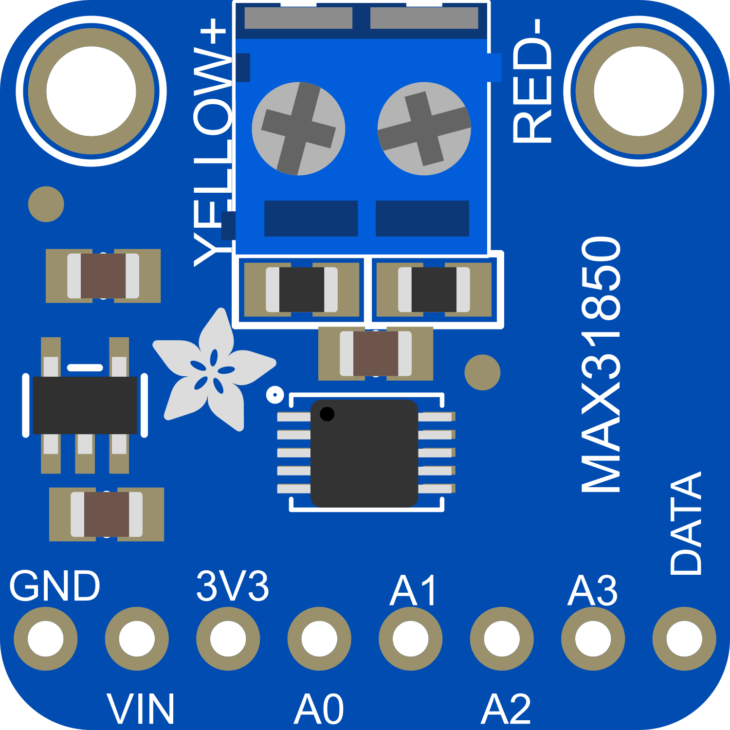
The Adafruit Thermocouple Amplifier with 1-Wire Breakout Board featuring the MAX31850K is a sophisticated electronic component designed to amplify the tiny voltage from a thermocouple to a more easily measurable level. It also digitizes the signal and communicates over a 1-Wire interface. This breakout board is commonly used in applications requiring precise temperature measurements, such as industrial systems, home brewing, and HVAC systems.
Explore Projects Built with Adafruit Thermocouple Amplifier with 1-Wire Breakout Board - MAX31850K
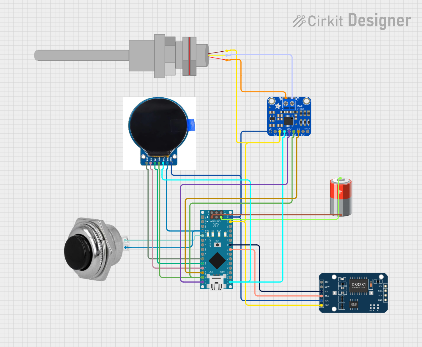
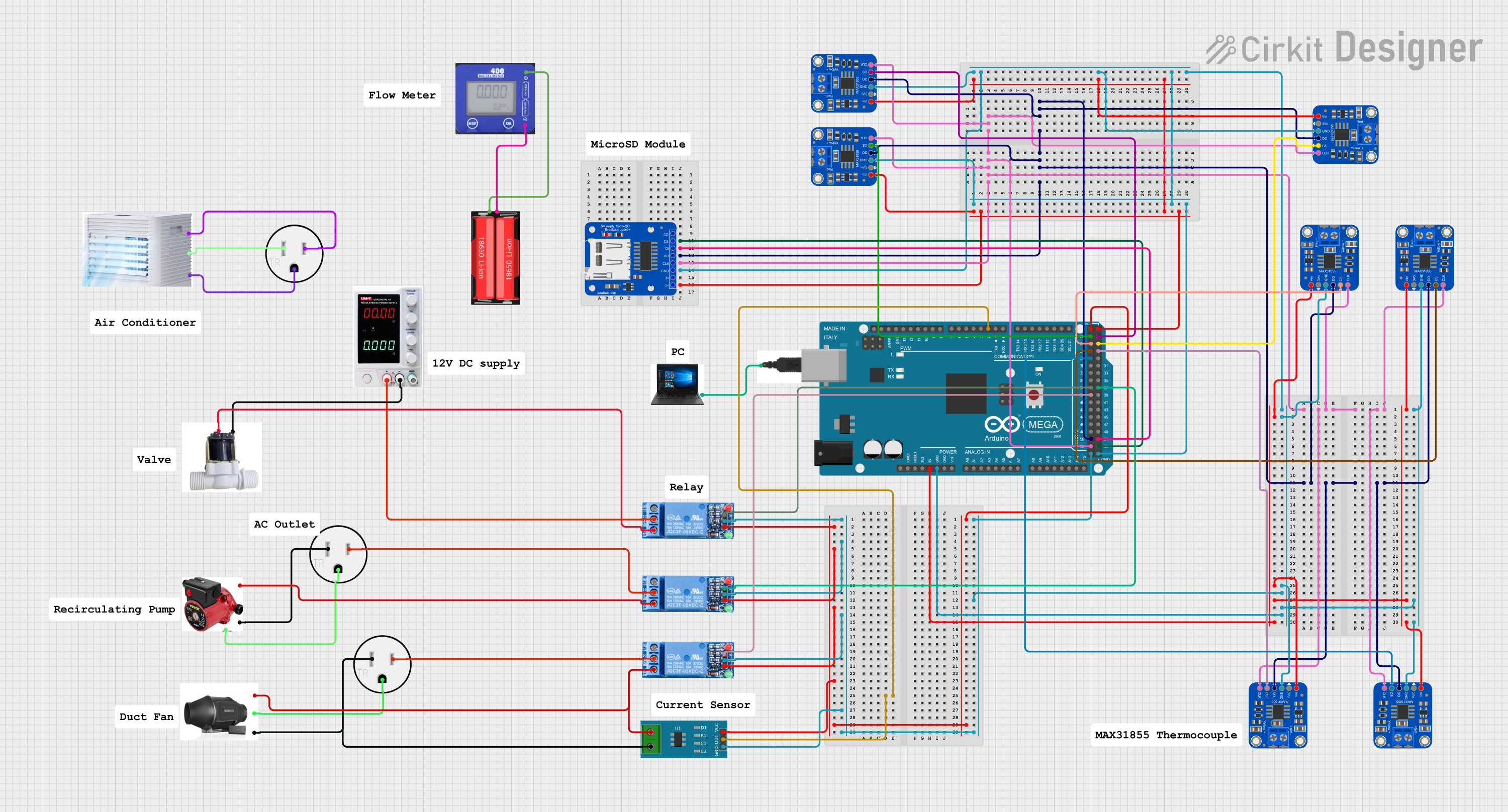

Explore Projects Built with Adafruit Thermocouple Amplifier with 1-Wire Breakout Board - MAX31850K
Technical Specifications
Key Technical Details
- Supply Voltage (VDD): 3.0V to 3.6V
- Operating Current: 1.5mA (typical)
- Temperature Resolution: 0.25°C (max)
- Temperature Accuracy: ±2°C (max)
- Temperature Range (Thermocouple): -200°C to +700°C
- Interface: 1-Wire
- Package: SOIC-8 surface mount
Pin Configuration and Descriptions
| Pin Number | Name | Description |
|---|---|---|
| 1 | GND | Ground connection for the power supply and signal reference. |
| 2 | DQ | 1-Wire data line, used for communication with the microcontroller. |
| 3 | VDD | Supply voltage input for the MAX31850K. |
| 4 | NC | No connection; this pin is not used. |
| 5 | NC | No connection; this pin is not used. |
| 6 | T- | Thermocouple negative input. |
| 7 | T+ | Thermocouple positive input. |
| 8 | NC | No connection; this pin is not used. |
Usage Instructions
How to Use the Component in a Circuit
- Power Supply: Connect the VDD pin to a 3.0V to 3.6V power source and the GND pin to the ground.
- Thermocouple Connection: Attach the thermocouple leads to the T+ and T- pins, ensuring correct polarity.
- Data Communication: Connect the DQ pin to a digital I/O pin on your microcontroller capable of 1-Wire communication.
- Pull-up Resistor: Attach a 4.7kΩ pull-up resistor between the DQ pin and VDD to ensure proper 1-Wire signal levels.
Important Considerations and Best Practices
- Ensure that the power supply is within the specified voltage range to prevent damage.
- Use twisted pair wires for the thermocouple to minimize electrical noise and improve measurement accuracy.
- Keep the breakout board away from heat sources other than the thermocouple to avoid false readings.
- Use proper ESD precautions when handling the breakout board to prevent damage to the sensitive electronics.
Troubleshooting and FAQs
Common Issues
- Inaccurate Temperature Readings: Ensure that the thermocouple is properly connected with the correct polarity and that there are no loose connections.
- No Data on 1-Wire Bus: Check the pull-up resistor on the DQ line and ensure that the microcontroller is correctly configured for 1-Wire communication.
Solutions and Tips for Troubleshooting
- If you encounter noise in the temperature readings, consider using a filter capacitor across the power supply pins or increasing the distance between the thermocouple wires and other electronic devices.
- For issues with the 1-Wire communication, verify that only one device is trying to communicate on the bus at a time, as the 1-Wire protocol is half-duplex.
FAQs
Q: Can I use this breakout board with any microcontroller? A: Yes, as long as the microcontroller supports 1-Wire communication and operates within the voltage range of the MAX31850K.
Q: How long can the thermocouple wires be? A: Thermocouple wires can be extended; however, the longer the wires, the more susceptible the system is to noise. Use twisted pair wires and keep the length reasonable.
Q: Is calibration necessary for accurate readings? A: The MAX31850K is factory-calibrated, but for critical applications, you may want to perform additional calibration to account for system-level inaccuracies.
Example Code for Arduino UNO
#include <OneWire.h>

// OneWire DS18S20, DS18B20, DS1822 Temperature Example
//
// http://www.pjrc.com/teensy/td_libs_OneWire.html

OneWire  ds(10);  // on pin 10 (a 4.7K resistor is necessary)

void setup(void) {
  Serial.begin(9600);
}

void loop(void) {
  byte i;
  byte present = 0;
  byte type_s;
  byte data[12];
  byte addr[8];
  float celsius, fahrenheit;

  if ( !ds.search(addr)) {
    Serial.println("No more addresses.");
    Serial.println();
    ds.reset_search();
    delay(250);
    return;
  }

  if (OneWire::crc8(addr, 7) != addr[7]) {
      Serial.println("CRC is not valid!");
      return;
  }
  Serial.println();

  // Match the address to the MAX31850K
  if (addr[0] == 0x3B) {
    type_s = 1;
  } else {
    Serial.println("Device is not a MAX31850K.");
    return;
  }

  ds.reset();
  ds.select(addr);
  ds.write(0x44, 1);        // start conversion, with parasite power on at the end

  delay(1000);     // maybe 750ms is enough, maybe not
  // we might do a ds.depower() here, but the reset will take care of it.

  present = ds.reset();
  ds.select(addr);
  ds.write(0xBE);         // Read Scratchpad

  for ( i = 0; i < 9; i++) {           // we need 9 bytes
    data[i] = ds.read();
  }

  // Convert the data to actual temperature
  // because the result is a 16 bit signed integer, it should
  // be stored to an "int16_t" type, which is always 16 bits
  // even when compiled on a 32 bit processor.
  int16_t raw = (data[1] << 8) | data[0];
  if (type_s) {
    raw = raw << 3; // 9 bit resolution default
    if (data[7] == 0x10) {
      // "count remain" gives full 12 bit resolution
      raw = (raw & 0xFFF0) + 12 - data[6];
    }
  } else {
    byte cfg = (data[4] & 0x60);
    // at lower res, the low bits are undefined, so let's zero them
    if (cfg == 0x00) raw = raw & ~7;  // 9 bit resolution, 93.75 ms
    else if (cfg == 0x20) raw = raw & ~3; // 10 bit res, 187.5 ms
    else if (cfg == 0x40) raw = raw & ~1; // 11 bit res, 375 ms
    //// default is 12 bit resolution, 750 ms conversion time
  }
  celsius = (float)raw / 16.0;
  fahrenheit = celsius * 1.8 + 32.0;
  Serial.print("  Temperature = ");
  Serial.print(celsius);
  Serial.print(" Celsius, ");
  Serial.print(fahrenheit);
  Serial.println(" Fahrenheit");
}
Note: This example code is for illustration purposes and may require modifications to work with the MAX31850K. Ensure that the correct device address is used and that the microcontroller's digital I/O pin matches the one defined in the code (OneWire ds(10); corresponds to pin 10 on the Arduino UNO).