How to Use b10k slide pots: Examples, Pinouts, and Specs
Introduction
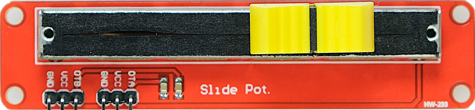
The B10K slide potentiometer is a variable resistor with a total resistance of 10k ohms. It features a sliding mechanism that allows users to adjust the resistance smoothly by moving the slider along a track. This component is widely used in applications requiring adjustable resistance, such as audio equipment for volume control, lighting dimmers, and other electronic devices where precise control of electrical signals is needed.
Explore Projects Built with b10k slide pots
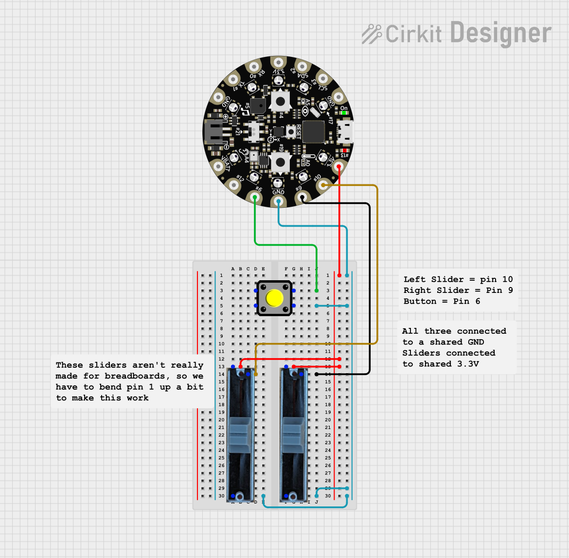

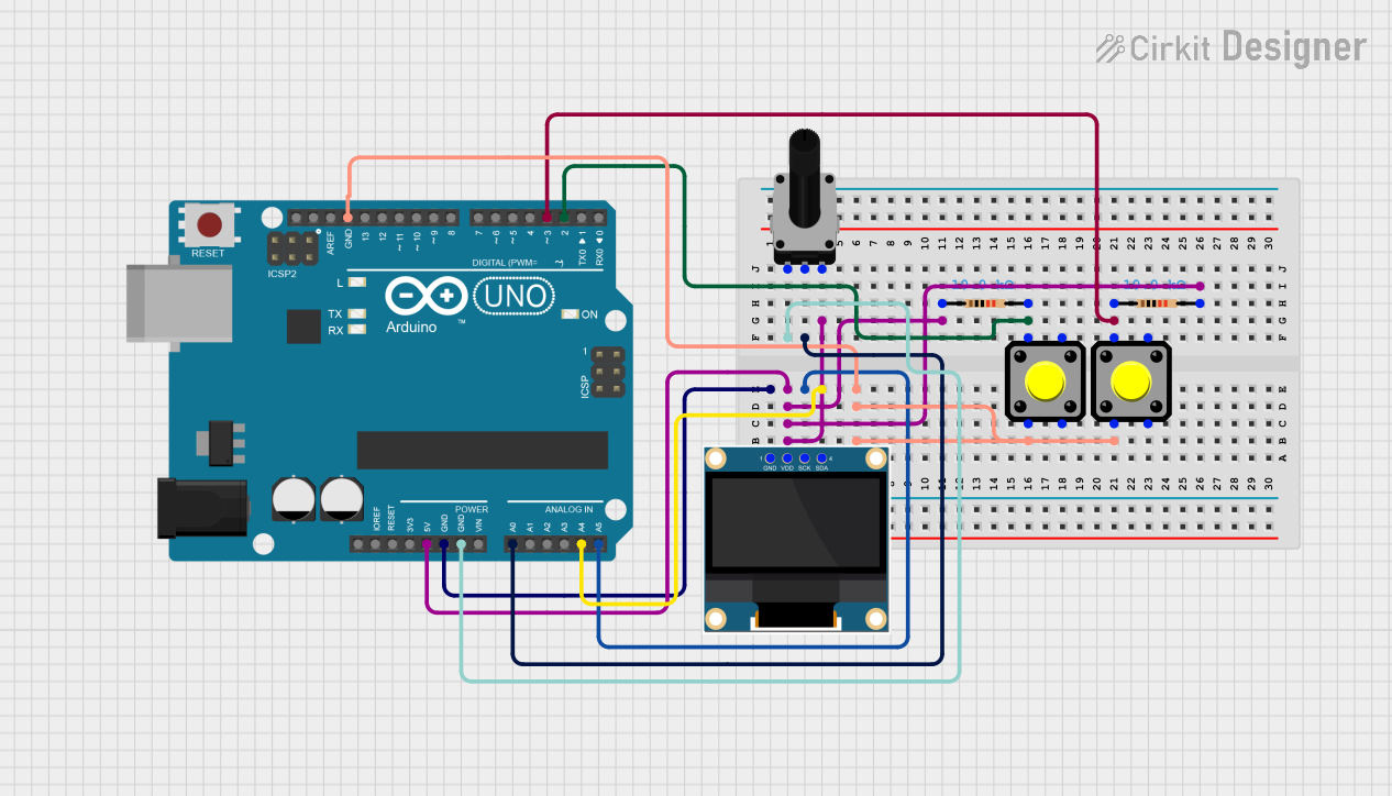
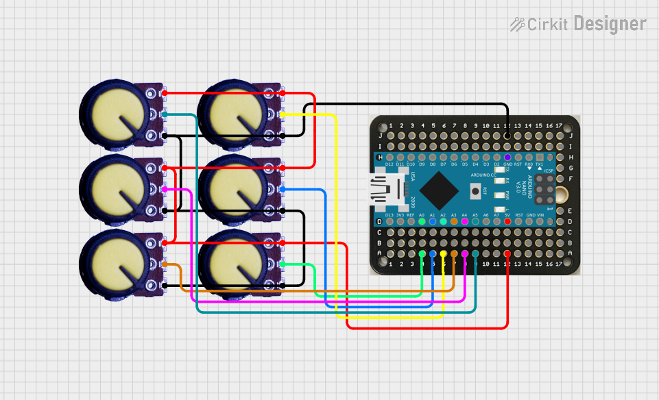
Explore Projects Built with b10k slide pots
Common Applications:
- Audio equipment (e.g., volume or tone control)
- Lighting dimmers
- Signal adjustment in analog circuits
- User interface controls in DIY electronics projects
- Adjustable voltage dividers
Technical Specifications
The B10K slide potentiometer is designed for ease of use and versatility. Below are its key technical details:
Key Specifications:
- Resistance: 10k ohms (B10K)
- Type: Linear taper (resistance changes linearly with slider movement)
- Operating Voltage: Typically up to 50V DC
- Power Rating: 0.1W to 0.5W (varies by model)
- Travel Length: Commonly 30mm to 60mm (depending on the model)
- Number of Terminals: 3 (two fixed terminals and one wiper terminal)
- Material: Metal and plastic construction
- Mounting Style: PCB mount or panel mount
Pin Configuration and Descriptions:
The B10K slide potentiometer has three terminals, as described in the table below:
| Pin Number | Name | Description |
|---|---|---|
| 1 | Terminal 1 | One end of the resistive track (fixed resistance point) |
| 2 | Wiper | The movable contact that slides along the resistive track to adjust output |
| 3 | Terminal 2 | The other end of the resistive track (fixed resistance point) |
Circuit Symbol:
The B10K slide potentiometer is represented in circuit diagrams as a resistor with an arrow pointing to the resistive track, indicating the adjustable wiper.
Usage Instructions
How to Use the B10K Slide Potentiometer in a Circuit:
Connect the Terminals:
- Connect Terminal 1 to the input voltage or signal source.
- Connect Terminal 2 to ground or the other end of the circuit.
- Connect the Wiper (Terminal 2) to the output where the adjusted signal is needed.
Adjust the Slider:
- Move the slider along the track to change the resistance. The output voltage or signal will vary depending on the slider's position.
Use as a Voltage Divider:
- The potentiometer can be used as a voltage divider by connecting Terminal 1 to a voltage source, Terminal 2 to ground, and the Wiper to the output. The output voltage will be proportional to the slider's position.
Important Considerations:
- Power Rating: Ensure the power dissipation across the potentiometer does not exceed its rated power.
- Linear Taper: The B10K slide potentiometer has a linear taper, meaning the resistance changes uniformly with slider movement.
- Mechanical Durability: Avoid excessive force on the slider to prevent damage to the track or wiper.
Example: Using the B10K Slide Potentiometer with an Arduino UNO
The B10K slide potentiometer can be used to provide an analog input to an Arduino UNO. Below is an example circuit and code:
Circuit Connections:
- Connect Terminal 1 to the 5V pin on the Arduino.
- Connect Terminal 2 to the GND pin on the Arduino.
- Connect the Wiper (Terminal 2) to an analog input pin (e.g., A0) on the Arduino.
Arduino Code:
// Example code to read the B10K slide potentiometer value and print it to the Serial Monitor

const int potPin = A0; // Define the analog pin connected to the potentiometer
int potValue = 0;      // Variable to store the potentiometer value

void setup() {
  Serial.begin(9600); // Initialize serial communication at 9600 baud
}

void loop() {
  potValue = analogRead(potPin); // Read the potentiometer value (0-1023)

  // Print the potentiometer value to the Serial Monitor
  Serial.print("Potentiometer Value: ");
  Serial.println(potValue);

  delay(100); // Add a small delay to avoid flooding the Serial Monitor
}
Best Practices:
- Use a decoupling capacitor (e.g., 0.1µF) across the potentiometer terminals to reduce noise in sensitive circuits.
- Avoid exceeding the voltage and current ratings to prevent damage.
- Secure the potentiometer firmly to the PCB or panel to ensure stable operation.
Troubleshooting and FAQs
Common Issues and Solutions:
Issue: The potentiometer output is noisy or unstable.
- Solution: Add a decoupling capacitor across the terminals to filter out noise.
Issue: The potentiometer does not vary the output as expected.
- Solution: Verify the connections. Ensure the wiper is connected to the output and the fixed terminals are connected to the input and ground.
Issue: The slider feels stuck or does not move smoothly.
- Solution: Check for physical obstructions or debris. Clean the track gently if necessary.
Issue: The potentiometer overheats or fails.
- Solution: Ensure the power dissipation does not exceed the rated power. Use a higher-rated potentiometer if needed.
FAQs:
Q: Can the B10K slide potentiometer be used for digital signals?
A: No, the potentiometer is designed for analog signals. It cannot directly process digital signals.Q: What does "B10K" mean?
A: "B" indicates a linear taper, and "10K" refers to the total resistance of 10k ohms.Q: Can I use the potentiometer to control an LED's brightness?
A: Yes, you can use the potentiometer as part of a voltage divider circuit to adjust the LED's brightness.Q: How do I mount the potentiometer?
A: The potentiometer can be mounted on a PCB or a panel, depending on the model. Ensure it is securely fastened to avoid movement during operation.
This concludes the documentation for the B10K slide potentiometer.