
How to Use Adafruit RFM96W LoRa Radio Transceiver Breakout - 433 MHz (RadioFruit): Examples, Pinouts, and Specs
 Design with Adafruit RFM96W LoRa Radio Transceiver Breakout - 433 MHz (RadioFruit) in Cirkit Designer
Introduction
The Adafruit RFM96W LoRa Radio Transceiver Breakout - 433 MHz (RadioFruit) (Manufacturer Part ID: ADA3073) is a low-power, long-range radio transceiver module designed for wireless communication in IoT applications. Operating at 433 MHz, this module leverages LoRa (Long Range) modulation technology to achieve extended communication ranges with minimal power consumption. Its compact design and high sensitivity make it ideal for applications such as remote sensing, environmental monitoring, smart agriculture, and other IoT-based systems.
Explore Projects Built with Adafruit RFM96W LoRa Radio Transceiver Breakout - 433 MHz (RadioFruit)
 Open Project in Cirkit Designer
 Open Project in Cirkit Designer
 Open Project in Cirkit Designer
 Open Project in Cirkit Designer
Explore Projects Built with Adafruit RFM96W LoRa Radio Transceiver Breakout - 433 MHz (RadioFruit)
Open Project in Cirkit DesignerOpen Project in Cirkit DesignerOpen Project in Cirkit DesignerOpen Project in Cirkit DesignerCommon Applications
- IoT Networks: Enables long-range communication between IoT devices.
- Remote Monitoring: Ideal for environmental sensors and telemetry systems.
- Smart Agriculture: Facilitates wireless communication in large agricultural fields.
- Home Automation: Supports wireless control of devices over long distances.
- Low-Power Wireless Networks: Suitable for battery-powered devices requiring extended range.
Technical Specifications
Key Technical Details
| Parameter | Value |
|---|---|
| Operating Frequency | 433 MHz |
| Modulation | LoRa (Long Range) |
| Sensitivity | Down to -148 dBm |
| Output Power | Up to +20 dBm |
| Operating Voltage | 3.3V to 5V |
| Current Consumption | 10.8 mA (Receive mode), 120 mA (Transmit mode at max power) |
| Communication Interface | SPI (Serial Peripheral Interface) |
| Dimensions | 25.5 mm x 18 mm x 3 mm |
| Operating Temperature Range | -40°C to +85°C |
| Antenna Connector | u.FL connector for external antenna |
Pin Configuration and Descriptions
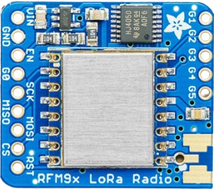
The RFM96W breakout board has 8 pins for interfacing with microcontrollers. Below is the pinout:
| Pin Name | Pin Number | Description |
|---|---|---|
| GND | 1 | Ground connection |
| VIN | 2 | Power input (3.3V to 5V) |
| SCK | 3 | SPI Clock signal |
| MISO | 4 | SPI Master-In-Slave-Out (data from module to microcontroller) |
| MOSI | 5 | SPI Master-Out-Slave-In (data from microcontroller to module) |
| CS | 6 | Chip Select (active low) |
| RST | 7 | Reset pin (active low) |
| G0 | 8 | General-purpose interrupt pin (used for signaling events like packet received) |
Usage Instructions
How to Use the Component in a Circuit
- Power Supply: Connect the
VINpin to a 3.3V or 5V power source and theGNDpin to ground. - SPI Communication: Connect the
SCK,MISO,MOSI, andCSpins to the corresponding SPI pins on your microcontroller. - Reset Pin: Connect the
RSTpin to a GPIO pin on your microcontroller for resetting the module. - Antenna: Attach an external antenna to the u.FL connector for optimal performance.
- Interrupt Pin: Optionally, connect the
G0pin to a GPIO pin on your microcontroller to handle interrupts.
Important Considerations and Best Practices
- Antenna Selection: Use a 433 MHz antenna for optimal range and performance.
- Power Supply: Ensure a stable power supply to avoid communication issues.
- SPI Configuration: Configure the SPI interface on your microcontroller to match the RFM96W's requirements (e.g., clock polarity and phase).
- LoRa Settings: Adjust LoRa parameters (e.g., spreading factor, bandwidth, coding rate) based on your application needs.
- Regulatory Compliance: Ensure compliance with local regulations for 433 MHz frequency usage.
Example Code for Arduino UNO
Below is an example of how to use the RFM96W with an Arduino UNO. This code uses the Adafruit RadioHead library for LoRa communication.
#include <SPI.h>
#include <RH_RF95.h>

// Define RFM96W pins
#define RFM95_CS 10  // Chip Select pin
#define RFM95_RST 9  // Reset pin
#define RFM95_INT 2  // Interrupt pin

// Define LoRa frequency
#define RF95_FREQ 433.0  // Frequency in MHz

// Create an instance of the RF95 driver
RH_RF95 rf95(RFM95_CS, RFM95_INT);

void setup() {
  // Initialize serial communication
  Serial.begin(9600);
  while (!Serial);

  // Initialize RFM96W module
  pinMode(RFM95_RST, OUTPUT);
  digitalWrite(RFM95_RST, HIGH);
  delay(10);
  digitalWrite(RFM95_RST, LOW);
  delay(10);
  digitalWrite(RFM95_RST, HIGH);
  delay(10);

  if (!rf95.init()) {
    Serial.println("LoRa initialization failed!");
    while (1);
  }
  Serial.println("LoRa initialization successful!");

  // Set frequency
  if (!rf95.setFrequency(RF95_FREQ)) {
    Serial.println("Failed to set frequency!");
    while (1);
  }
  Serial.print("Frequency set to: ");
  Serial.println(RF95_FREQ);

  // Set transmit power (max 23 dBm)
  rf95.setTxPower(20, false);
}

void loop() {
  // Send a test message
  Serial.println("Sending message...");
  const char *msg = "Hello, LoRa!";
  rf95.send((uint8_t *)msg, strlen(msg));
  rf95.waitPacketSent();
  Serial.println("Message sent!");

  // Wait for a response
  if (rf95.waitAvailableTimeout(3000)) {
    uint8_t buf[RH_RF95_MAX_MESSAGE_LEN];
    uint8_t len = sizeof(buf);
    if (rf95.recv(buf, &len)) {
      Serial.print("Received: ");
      Serial.println((char *)buf);
    } else {
      Serial.println("Receive failed!");
    }
  } else {
    Serial.println("No response received.");
  }

  delay(5000);  // Wait 5 seconds before sending the next message
}
Troubleshooting and FAQs
Common Issues and Solutions
Module Not Initializing:
- Ensure all connections are secure and correct.
- Verify that the
RSTpin is properly connected and toggled during initialization. - Check the power supply voltage (3.3V to 5V).
No Communication:
- Verify that the SPI pins are correctly connected and configured.
- Ensure the LoRa frequency matches on both transmitter and receiver modules.
- Check the antenna connection for proper placement and compatibility.
Short Range:
- Use a high-quality 433 MHz antenna.
- Avoid obstructions and interference in the communication path.
- Increase the transmit power using the
setTxPower()function.
High Power Consumption:
- Use low-power modes when the module is idle.
- Optimize the duty cycle of transmissions to reduce energy usage.
FAQs
Can I use this module with a 5V microcontroller? Yes, the module supports 5V logic levels, but ensure the power supply is stable.
What is the maximum range of this module? The range depends on environmental conditions, antenna quality, and LoRa settings. It can reach several kilometers in open areas.
Is this module compatible with other LoRa devices? Yes, as long as the frequency and LoRa settings match.
Can I use multiple modules in the same area? Yes, but ensure unique addresses or channels to avoid interference.