How to Use 7805: Examples, Pinouts, and Specs
Introduction
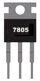
The 7805 is a linear voltage regulator that provides a stable output voltage of 5V. It is part of the 78xx series of voltage regulators, which are designed to deliver a fixed output voltage while maintaining stability and protecting connected components from voltage fluctuations. The 7805 is widely used in electronic circuits to power microcontrollers, sensors, and other components that require a consistent 5V supply. Its ease of use, reliability, and built-in protection features make it a popular choice for both hobbyists and professionals.
Explore Projects Built with 7805

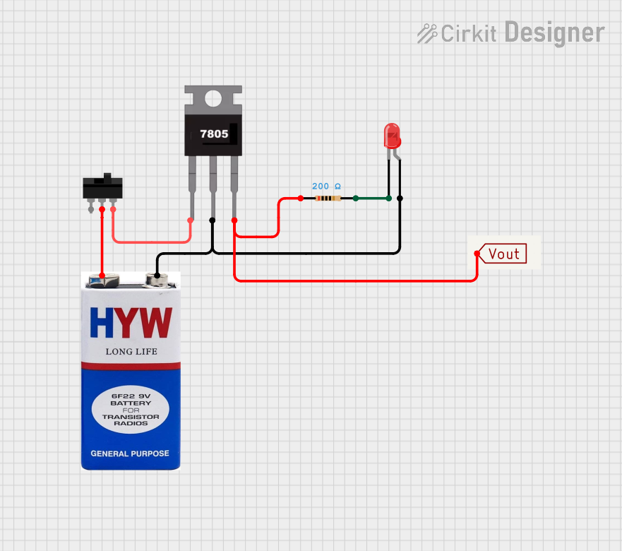
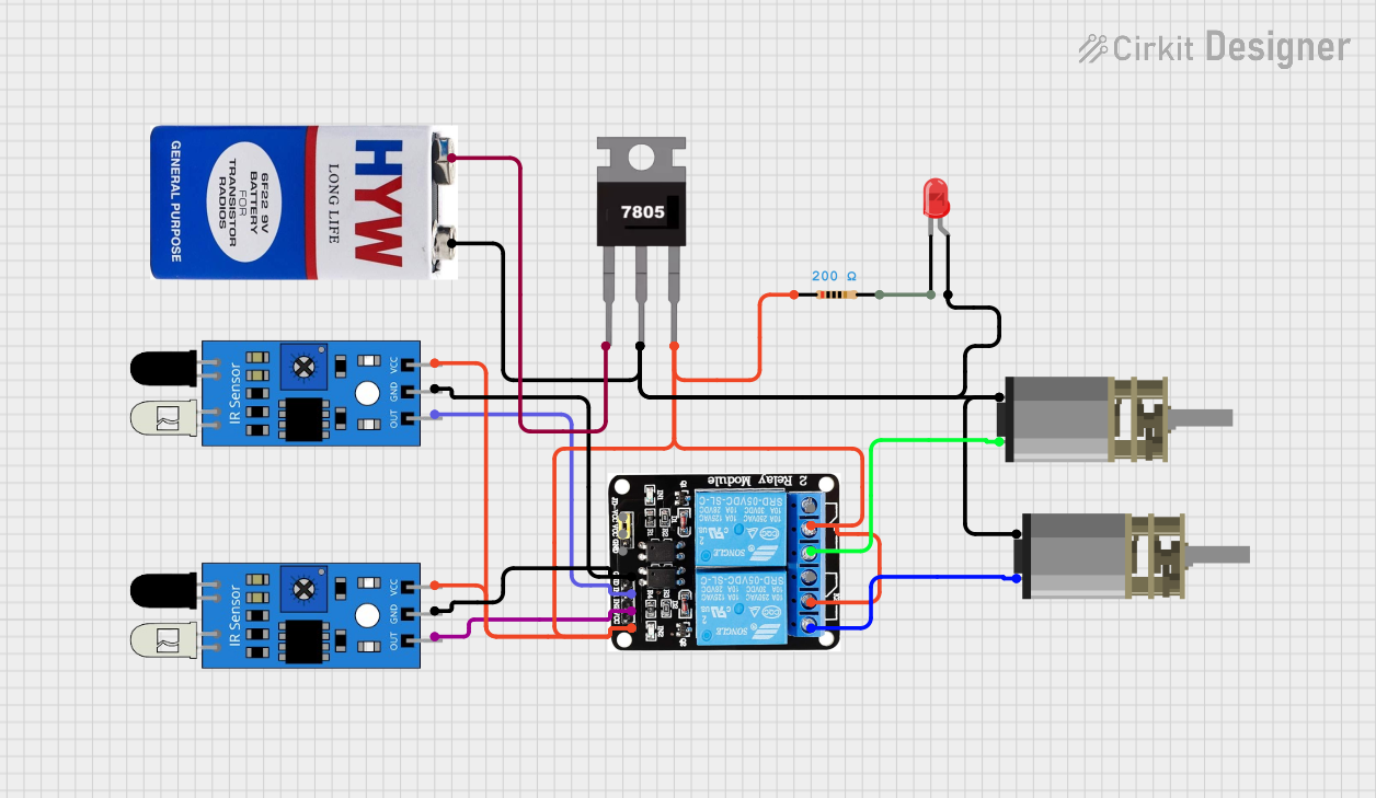

Explore Projects Built with 7805
Common Applications and Use Cases
- Powering microcontrollers (e.g., Arduino, Raspberry Pi peripherals)
- Regulating voltage for sensors and modules
- Providing a stable 5V supply in battery-powered devices
- Used in DIY electronics projects and prototyping
- Voltage regulation in power supply circuits
Technical Specifications
The 7805 voltage regulator has the following key technical specifications:
| Parameter | Value |
|---|---|
| Output Voltage | 5V ± 2% |
| Input Voltage Range | 7V to 35V |
| Maximum Output Current | 1A (with proper heat sinking) |
| Dropout Voltage | 2V to 2.5V |
| Quiescent Current | 5mA to 8mA |
| Operating Temperature | 0°C to 125°C |
| Package Types | TO-220, TO-92, SMD |
| Built-in Protections | Overheat, Overcurrent, Short Circuit |
Pin Configuration and Descriptions
The 7805 typically comes in a TO-220 package with three pins. The pinout is as follows:
| Pin Number | Name | Description |
|---|---|---|
| 1 | Input | Connect to the unregulated input voltage (7V–35V). |
| 2 | Ground | Common ground for input and output. |
| 3 | Output | Provides the regulated 5V output. |
Usage Instructions
How to Use the 7805 in a Circuit
- Input Voltage: Connect a DC voltage source (7V–35V) to the input pin of the 7805. Ensure the input voltage is at least 2V higher than the desired 5V output to account for the dropout voltage.
- Ground Connection: Connect the ground pin of the 7805 to the ground of your circuit.
- Output Voltage: Connect the output pin to the load that requires a 5V supply.
- Capacitors: Add capacitors to stabilize the voltage and reduce noise:
- Place a 0.33µF capacitor between the input pin and ground.
- Place a 0.1µF capacitor between the output pin and ground.
- Heat Sink: If the load draws significant current (close to 1A), attach a heat sink to the 7805 to prevent overheating.
Example Circuit
Below is a simple circuit diagram for using the 7805:
   +7V to +35V
       |
       |
      [C1]  0.33µF
       |
       |-----> Pin 1 (Input)
       |
      7805
       |
       |-----> Pin 2 (Ground) -----> Circuit Ground
       |
      [C2]  0.1µF
       |
       |-----> Pin 3 (Output) -----> +5V to Load
Using the 7805 with an Arduino UNO
The 7805 can be used to power an Arduino UNO by providing a stable 5V supply. Below is an example of how to connect the 7805 to an Arduino UNO:
- Connect the input pin of the 7805 to a 9V battery or DC adapter.
- Connect the ground pin of the 7805 to the GND pin of the Arduino.
- Connect the output pin of the 7805 to the 5V pin of the Arduino.
Example Arduino Code
// Example code to blink an LED using an Arduino UNO powered by a 7805 regulator
// Ensure the 7805 is providing a stable 5V to the Arduino's 5V pin.

const int ledPin = 13; // Built-in LED pin on Arduino UNO

void setup() {
  pinMode(ledPin, OUTPUT); // Set the LED pin as an output
}

void loop() {
  digitalWrite(ledPin, HIGH); // Turn the LED on
  delay(1000);                // Wait for 1 second
  digitalWrite(ledPin, LOW);  // Turn the LED off
  delay(1000);                // Wait for 1 second
}
Important Considerations and Best Practices
- Input Voltage: Ensure the input voltage is at least 2V higher than the output voltage (minimum 7V for a 5V output).
- Heat Dissipation: Use a heat sink if the regulator gets too hot during operation.
- Capacitors: Always use input and output capacitors to improve stability and reduce noise.
- Current Limit: Do not exceed the maximum output current of 1A. Use a higher-rated regulator if your circuit requires more current.
Troubleshooting and FAQs
Common Issues and Solutions
Output Voltage is Not 5V:
- Check the input voltage. Ensure it is within the range of 7V to 35V.
- Verify the connections and ensure the ground pin is properly connected.
- Add or replace the input and output capacitors to stabilize the voltage.
Regulator Overheats:
- Attach a heat sink to the 7805 to dissipate heat.
- Reduce the load current if it exceeds 1A.
- Ensure proper ventilation around the regulator.
No Output Voltage:
- Check for short circuits or incorrect wiring.
- Verify that the input voltage is present and within the required range.
- Replace the 7805 if it is damaged.
Noise or Voltage Fluctuations:
- Add capacitors (0.33µF on the input and 0.1µF on the output) to reduce noise.
- Ensure the input voltage source is stable and free from significant fluctuations.
FAQs
Q: Can I use the 7805 to power a 3.3V device?
A: No, the 7805 provides a fixed 5V output. To power a 3.3V device, use a 3.3V regulator like the 7833 or a buck converter.
Q: What happens if I connect an input voltage below 7V?
A: The 7805 may not regulate properly, and the output voltage could drop below 5V, causing instability in your circuit.
Q: Can I use the 7805 without capacitors?
A: While the 7805 can function without capacitors, it is highly recommended to use them to ensure stable operation and reduce noise.
Q: Is the 7805 suitable for battery-powered devices?
A: Yes, but ensure the battery voltage is within the input range (7V–35V) and consider the power loss due to heat dissipation.
By following this documentation, you can effectively use the 7805 voltage regulator in your electronic projects.