How to Use Adafruit CCS811: Examples, Pinouts, and Specs
Introduction
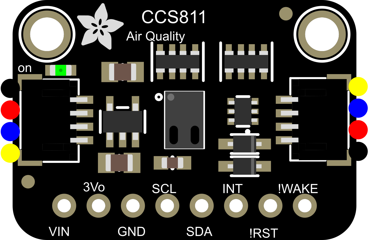
The Adafruit CCS811 is an advanced gas sensor designed to detect a wide range of Volatile Organic Compounds (VOCs) and equivalent carbon dioxide (eCO2) levels. This sensor is ideal for monitoring indoor air quality in various environments such as homes, offices, and industrial spaces. The CCS811 is a digital sensor that communicates over an I2C interface, making it easy to integrate with microcontrollers like the Arduino UNO.
Explore Projects Built with Adafruit CCS811
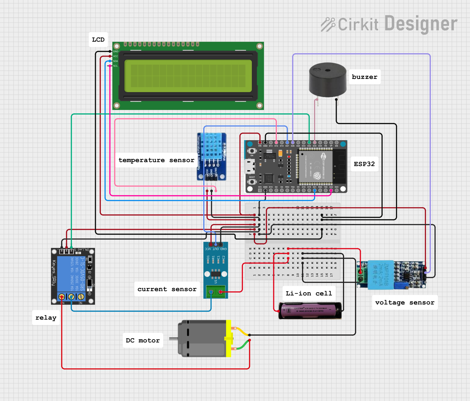
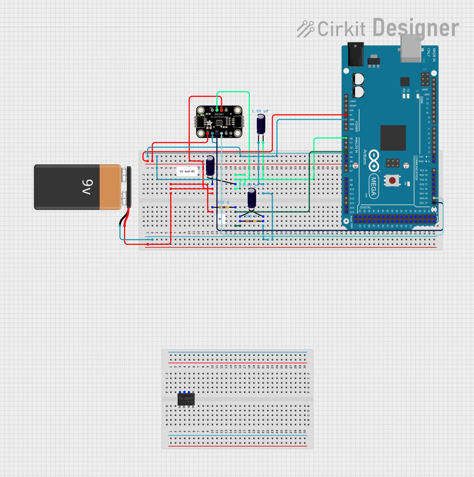


Explore Projects Built with Adafruit CCS811
Common Applications and Use Cases
- Indoor air quality monitoring
- Smart home automation systems
- HVAC system monitoring
- Environmental monitoring
Technical Specifications
Key Technical Details
- Measurement Range (eCO2): 400 to 8192 parts per million (ppm)
- Measurement Range (TVOC): 0 to 1187 parts per billion (ppb)
- Interface: I2C
- Supply Voltage: 3.3V to 5V
- Current Consumption: 30mA (typical during measurement)
- Operating Temperature: -40°C to 85°C
Pin Configuration and Descriptions
| Pin Number | Pin Name | Description |
|---|---|---|
| 1 | VDD | Supply Voltage (3.3V to 5V) |
| 2 | GND | Ground |
| 3 | SDA | I2C Data |
| 4 | SCL | I2C Clock |
| 5 | WAKE | Wake Pin (active low) |
| 6 | INT | Interrupt Pin |
| 7 | RST | Reset Pin (active low) |
| 8 | ADDR | I2C Address Select (float or connect to GND) |
Usage Instructions
Integrating with a Circuit
- Powering the Sensor: Connect the VDD pin to a 3.3V or 5V power supply and the GND pin to the ground.
- I2C Communication: Connect the SDA and SCL pins to the corresponding SDA and SCL pins on your microcontroller.
- Wake Pin: The WAKE pin can be connected to ground to keep the sensor awake.
- Interrupt and Reset: The INT and RST pins can be left unconnected if not used. If using the interrupt feature, connect the INT pin to an interrupt-capable GPIO on your microcontroller. The RST pin can be connected to a GPIO for software reset functionality.
Important Considerations and Best Practices
- Ensure that the sensor is not exposed to solvents or chemicals that could damage the sensor.
- Avoid placing the sensor in environments with high humidity for extended periods.
- Allow the sensor to preheat for 20 minutes upon first use for accurate readings.
- Use pull-up resistors on the I2C lines if your microcontroller does not have built-in pull-ups.
Example Code for Arduino UNO
#include <Wire.h>
#include <Adafruit_CCS811.h>

Adafruit_CCS811 ccs;

void setup() {
  Serial.begin(9600);
  Wire.begin();

  // Initialize the sensor
  if (!ccs.begin()) {
    Serial.println("Failed to start sensor! Please check your wiring.");
    while (1);
  }

  // Wait for the sensor to be ready
  while (!ccs.available());
}

void loop() {
  // Read sensor data when available
  if (ccs.available()) {
    if (!ccs.readData()) {
      Serial.print("CO2: ");
      Serial.print(ccs.geteCO2());
      Serial.print("ppm, TVOC: ");
      Serial.print(ccs.getTVOC());
      Serial.println("ppb");
    } else {
      Serial.println("ERROR!");
      // If reading the sensor data failed, print an error message
    }
  }
  delay(500); // Wait for 500 ms before reading again
}
Troubleshooting and FAQs
Common Issues
- Sensor Not Responding: Ensure that the sensor is correctly powered and that the I2C connections are secure.
- Inaccurate Readings: Make sure the sensor has been preheated and is not exposed to contaminants.
- I2C Communication Errors: Check for proper pull-up resistors on the SDA and SCL lines.
Solutions and Tips for Troubleshooting
- Power Cycle the Sensor: If the sensor is unresponsive, try disconnecting and reconnecting the power.
- Check I2C Address: Verify that the I2C address configured in your code matches the address set by the ADDR pin.
- Sensor Calibration: Follow the manufacturer's guidelines for calibrating the sensor for more accurate readings.
FAQs
Q: Can the CCS811 sensor measure CO2 directly? A: No, the CCS811 measures eCO2 levels, which are calculated based on detected VOCs and not a direct measurement of CO2.
Q: How long does the sensor need to preheat? A: The sensor should preheat for at least 20 minutes upon first use or after a prolonged period of inactivity.
Q: Is the sensor compatible with 5V logic? A: The sensor can be powered by 5V, but the logic level for I2C communication is 3.3V. Use level shifters if necessary.
Q: Can I use multiple CCS811 sensors on the same I2C bus? A: Yes, but you will need to set different I2C addresses using the ADDR pin for each sensor.