How to Use PowerBoost 1000 Basic Terminal Pad: Examples, Pinouts, and Specs
Introduction
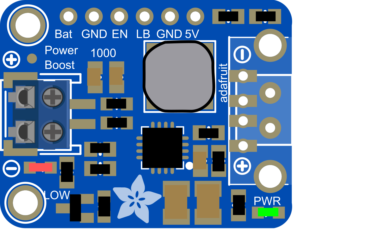
The PowerBoost 1000 Basic Terminal Pad is a versatile power supply module designed to provide a reliable power source for your electronics projects. It is similar to the PowerBoost 1000 Basic with a USB output but instead features output terminals for direct wiring to your project. This component is ideal for portable devices, wearables, and any application requiring a stable 5V supply from battery sources.
Explore Projects Built with PowerBoost 1000 Basic Terminal Pad

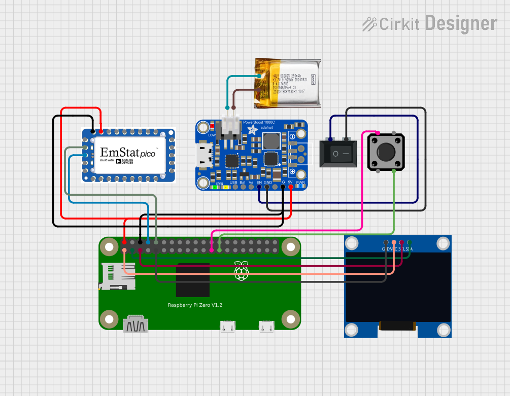
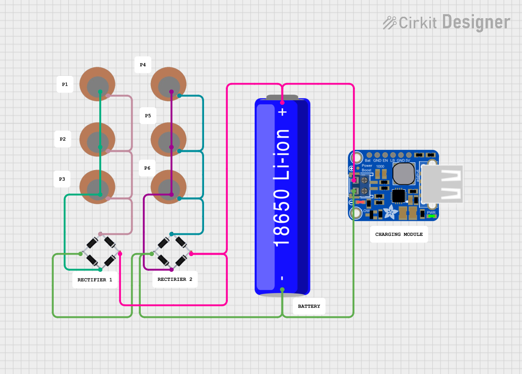
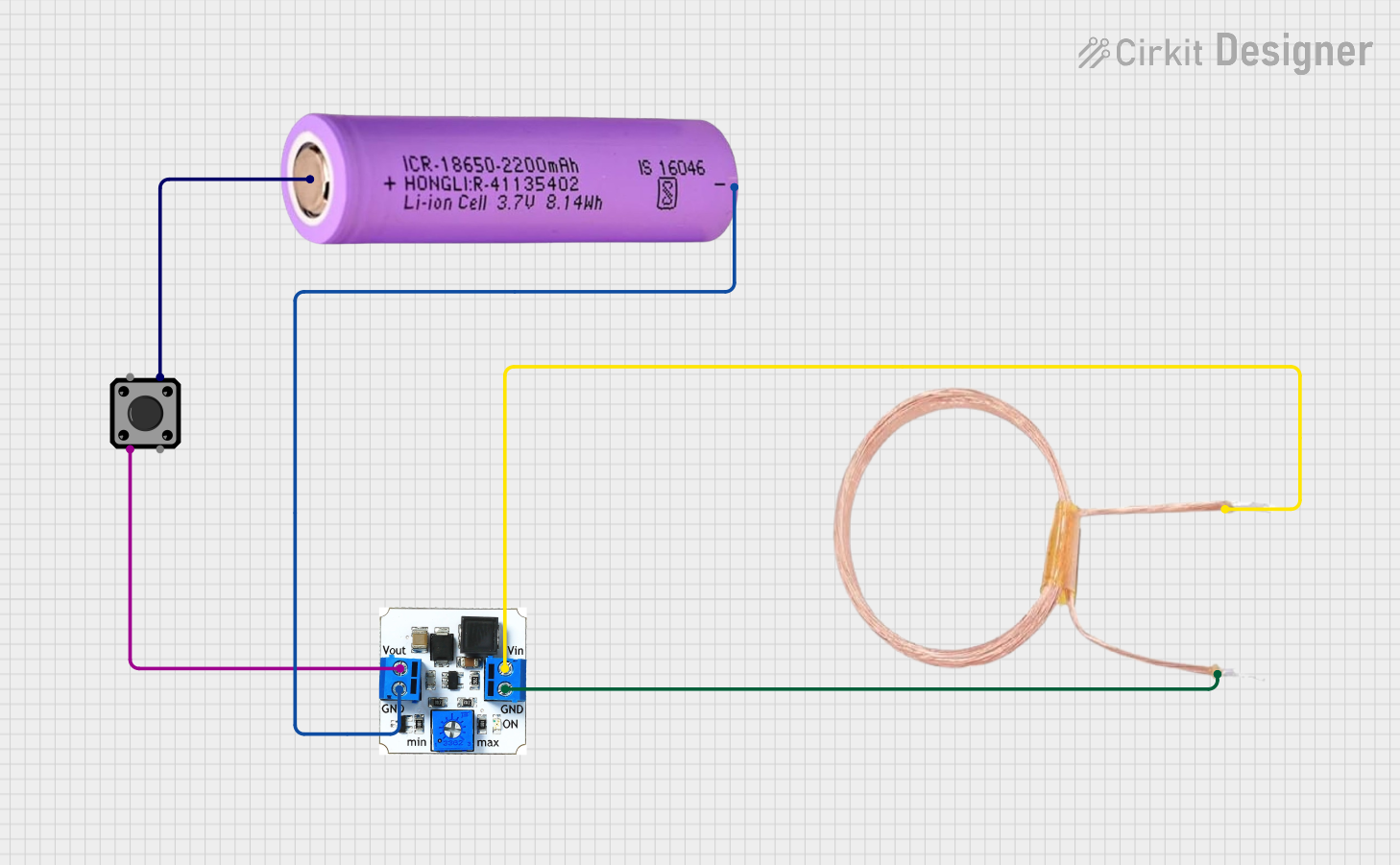
Explore Projects Built with PowerBoost 1000 Basic Terminal Pad
Common Applications and Use Cases
- Portable electronics
- Wearable devices
- Battery-powered projects
- DIY power banks
- Robotics
Technical Specifications
Key Technical Details
- Input Voltage: 1.8V to 5.5V
- Output Voltage: 5V regulated
- Peak Output Current: 1A (with heat sinking)
- Quiescent Current: 5mA typical (when idle)
- Efficiency: 90%+ (higher input voltages, lower output currents)
- Switching Frequency: 1.2MHz
Pin Configuration and Descriptions
| Pin Name | Description |
|---|---|
| VIN | Input voltage (1.8V to 5.5V) |
| GND | Ground connection |
| 5V | Regulated 5V output |
| EN | Enable pin (pull low to disable) |
| BAT | Battery connection for charging |
Usage Instructions
How to Use the Component in a Circuit
Connect the Battery:
- Connect your battery to the
BATandGNDterminals. Ensure the battery voltage is within the specified input range.
- Connect your battery to the
Enable the PowerBoost:
- The
ENpin can be left unconnected for normal operation, as it is internally pulled high. To disable the PowerBoost, connect theENpin toGND.
- The
Connect the Load:
- Connect your load to the
5VandGNDterminals. Ensure the load does not exceed the peak output current rating.
- Connect your load to the
Important Considerations and Best Practices
Heat Management:
- If drawing currents near the peak rating, ensure adequate heat sinking or airflow over the module to prevent overheating.
Input Voltage:
- Do not exceed the maximum input voltage to prevent damage to the PowerBoost.
Battery Charging:
- The PowerBoost does not include battery charging circuitry. Ensure your battery has its own charging protection.
Enable Pin Usage:
- If you use the
ENpin to control the module, use a pull-up resistor if your control signal is not guaranteed to be high.
- If you use the
Troubleshooting and FAQs
Common Issues
PowerBoost Does Not Turn On:
- Check battery voltage and connections.
- Ensure the
ENpin is not inadvertently pulled low.
Output Voltage is Unstable or Too Low:
- Verify that the load does not exceed the peak current rating.
- Check for adequate heat dissipation.
PowerBoost Overheats:
- Reduce the load current or improve heat sinking/airflow.
Solutions and Tips for Troubleshooting
Check Connections:
- Ensure all connections are secure and free from corrosion or damage.
Measure Input Voltage:
- Use a multimeter to confirm the input voltage is within the specified range.
Inspect for Physical Damage:
- Look for signs of overheating, such as discolored components or melted plastic.
FAQs
Can I use the PowerBoost 1000 Basic Terminal Pad to charge batteries?
- No, this module does not include battery charging functionality.
What is the maximum input voltage for the PowerBoost 1000 Basic Terminal Pad?
- The maximum input voltage is 5.5V. Exceeding this may damage the module.
Can I use multiple PowerBoosts in parallel to increase current capacity?
- It is not recommended to use switching power supplies like the PowerBoost in parallel due to potential issues with load sharing and phase synchronization.
For further assistance or technical support, please contact the manufacturer or visit the community forums dedicated to electronics enthusiasts.