How to Use Adafruit PDM Mic with JST: Examples, Pinouts, and Specs
Introduction
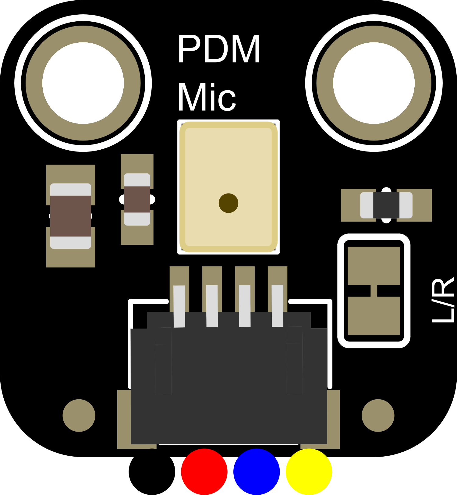
The Adafruit PDM Mic with JST is a compact and versatile sound sensor module that captures high-quality audio signals using Pulse-Density Modulation (PDM). This microphone is ideal for a variety of applications, including sound detection, voice recognition, and audio recording in embedded systems. Its small form factor and simple interface make it a popular choice for hobbyists and professionals working on projects with microcontrollers like the Arduino UNO.
Explore Projects Built with Adafruit PDM Mic with JST
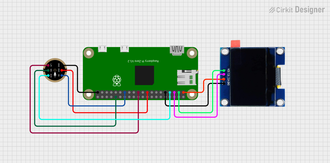
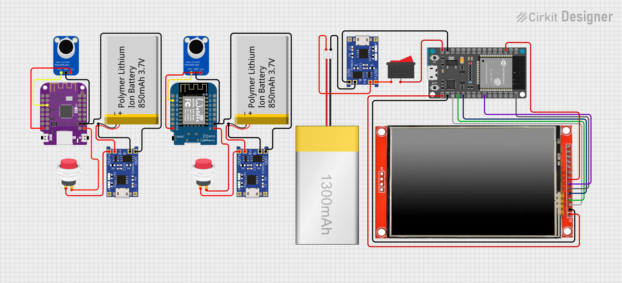

Explore Projects Built with Adafruit PDM Mic with JST
Technical Specifications
Key Technical Details
- Microphone Type: Digital PDM MEMS
- Operating Voltage: 3.3V to 5V
- Current Consumption: Typically 650 µA
- Sensitivity: -26 dBFS (decibels relative to full scale)
- Signal to Noise Ratio (SNR): 65 dB
- Sample Rate: Adjustable up to 1 to 3.25 MHz
- Interface: JST SH 4-pin connector with 1mm pitch
Pin Configuration and Descriptions
| Pin Number | Name | Description |
|---|---|---|
| 1 | SEL | Select pin for mode configuration (floating or tied to GND) |
| 2 | DAT | PDM data output |
| 3 | CLK | Clock input for PDM data |
| 4 | GND | Ground connection |
Usage Instructions
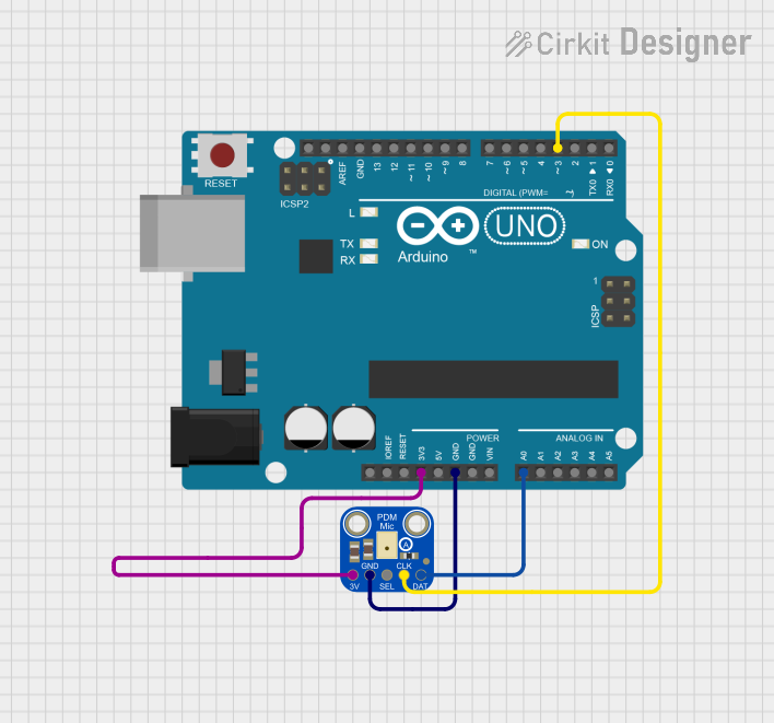
Integration with a Circuit
To use the Adafruit PDM Mic with JST in a circuit:
- Connect the SEL pin to GND if you want to use the left channel. Leave it floating for the right channel.
- Connect the DAT pin to the data input on your microcontroller.
- Connect the CLK pin to a clock output capable of generating the required frequency.
- Connect the GND pin to the ground of your power supply and microcontroller.
Important Considerations and Best Practices
- Ensure that the power supply is within the operating voltage range.
- Use a pull-up resistor on the DAT line if your microcontroller does not have one built-in.
- Keep the microphone away from noise sources such as motors or high-frequency signals.
- Use proper decoupling capacitors close to the power pins to minimize power supply noise.
Example Code for Arduino UNO
#include <PDM.h>

// Define the CLK and DAT pins
const int clkPin = 2; // Connect to CLK pin of the microphone
const int datPin = 3; // Connect to DAT pin of the microphone

// Buffer to store audio samples
short buffer[512];

void onPDMdata() {
  // Callback function to process PDM data
  int bytesAvailable = PDM.available();
  PDM.read(buffer, bytesAvailable);
}

void setup() {
  // Initialize serial communication
  Serial.begin(9600);

  // Configure the CLK and DAT pins
  PDM.begin(clkPin, datPin);

  // Set up the PDM microphone
  PDM.setBufferSize(512);
  PDM.onReceive(onPDMdata);
  PDM.setGain(20);
  PDM.setSampleRate(16000); // Set the sample rate to 16 kHz
}

void loop() {
  // Main loop does nothing, audio processing is done in onPDMdata
}
Troubleshooting and FAQs
Common Issues
- No Sound Detected: Ensure that the microphone is correctly powered and that the SEL pin is configured for the desired channel.
- Distorted Audio: Check the clock frequency and ensure it's within the specified range for the microphone.
- Low Volume: Adjust the gain setting in the code or check the microphone's placement and orientation.
Solutions and Tips
- Verify all connections and solder joints for any loose or cold solder points.
- Use an oscilloscope to check the clock signal and data output for expected waveforms.
- Ensure that the Arduino library for PDM is up to date and properly included in your project.
FAQs
Q: Can I use this microphone with a 5V microcontroller? A: Yes, the microphone can operate with 3.3V to 5V, but ensure that the logic levels for data and clock are compatible with your microcontroller.
Q: How do I change the sample rate?
A: The sample rate can be adjusted in the setup function using PDM.setSampleRate().
Q: What is the maximum distance the microphone can pick up sound? A: The effective range depends on the ambient noise and the sound volume. For clear audio, it is recommended to keep the source within a few feet of the microphone.
Remember to follow all safety precautions when working with electronic components and ensure that your work area is well-ventilated and free from static discharge.