
How to Use SparkFun Thing Plus Wroom E: Examples, Pinouts, and Specs
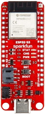
 Design with SparkFun Thing Plus Wroom E in Cirkit Designer
Introduction
The SparkFun Thing Plus Wroom E is a compact development board built around the ESP32 WROOM module. It is designed for Internet of Things (IoT) applications, offering built-in Wi-Fi and Bluetooth capabilities. This board is ideal for projects requiring wireless communication, sensor integration, and peripheral control. Its small form factor and compatibility with the Feather ecosystem make it a versatile choice for both hobbyists and professionals.
Explore Projects Built with SparkFun Thing Plus Wroom E
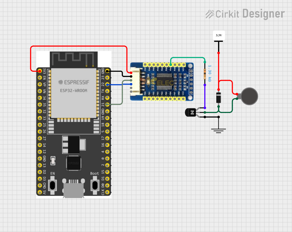 Open Project in Cirkit Designer
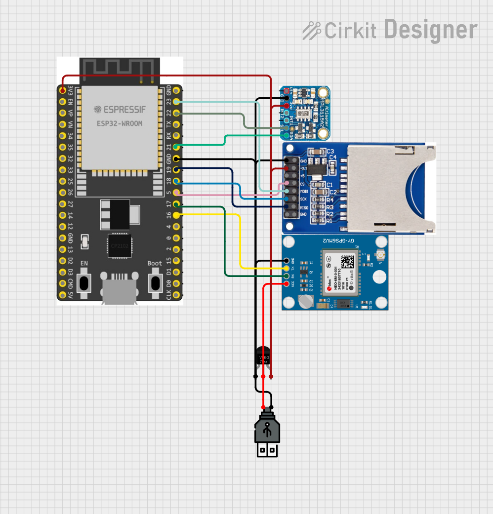 Open Project in Cirkit Designer
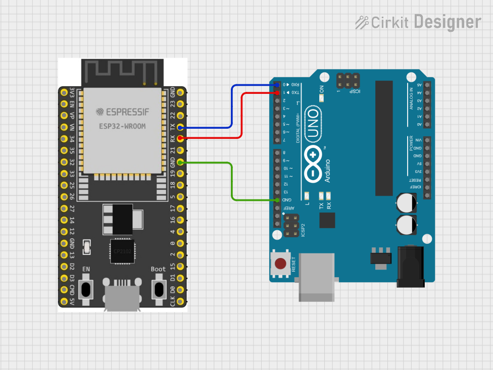 Open Project in Cirkit Designer
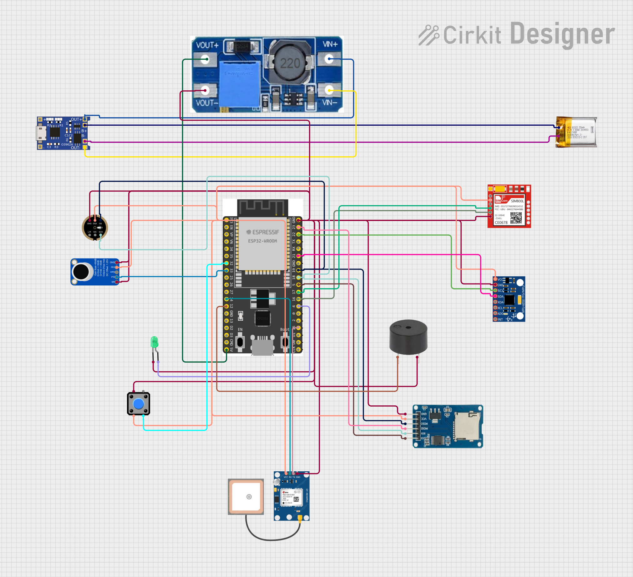 Open Project in Cirkit Designer
Explore Projects Built with SparkFun Thing Plus Wroom E
Open Project in Cirkit DesignerOpen Project in Cirkit DesignerOpen Project in Cirkit DesignerOpen Project in Cirkit DesignerCommon Applications and Use Cases
- IoT devices and smart home automation
- Wireless sensor networks
- Wearable technology
- Robotics and remote control systems
- Data logging and monitoring
- Prototyping and development of Bluetooth and Wi-Fi-enabled devices
Technical Specifications
The SparkFun Thing Plus Wroom E is powered by the ESP32 WROOM module, which features a dual-core processor and integrated wireless communication capabilities. Below are the key technical details:
Key Specifications
| Specification | Value |
|---|---|
| Microcontroller | ESP32 WROOM module |
| Processor | Dual-core Xtensa® 32-bit LX6 @ 240 MHz |
| Flash Memory | 4 MB |
| SRAM | 520 KB |
| Wi-Fi | 802.11 b/g/n (2.4 GHz) |
| Bluetooth | Bluetooth v4.2 BR/EDR and BLE |
| Operating Voltage | 3.3V |
| Input Voltage (VIN) | 5V (via USB-C) |
| GPIO Pins | 21 (multipurpose, including ADC, PWM, etc.) |
| ADC Channels | 18 |
| DAC Channels | 2 |
| Communication Interfaces | UART, SPI, I2C, I2S |
| USB Interface | USB-C for programming and power |
| Dimensions | 2.0" x 0.9" (50.8 mm x 22.86 mm) |
Pin Configuration and Descriptions
The SparkFun Thing Plus Wroom E features a Feather-compatible pin layout. Below is the pin configuration:
| Pin Name | Function | Description |
|---|---|---|
| VIN | Power Input | Accepts 5V input via USB-C or external |
| 3.3V | Power Output | Regulated 3.3V output |
| GND | Ground | Common ground for the circuit |
| GPIO0 | General Purpose I/O | Can be used for ADC, PWM, or digital I/O |
| GPIO1 | UART TX | Transmit pin for UART communication |
| GPIO3 | UART RX | Receive pin for UART communication |
| GPIO21 | I2C SDA | Data line for I2C communication |
| GPIO22 | I2C SCL | Clock line for I2C communication |
| GPIO25 | DAC1 | Digital-to-Analog Converter channel 1 |
| GPIO26 | DAC2 | Digital-to-Analog Converter channel 2 |
| EN | Enable | Resets the board when pulled low |
| RST | Reset | Resets the microcontroller |
Usage Instructions
How to Use the Component in a Circuit
Powering the Board:
- Connect the board to a computer or USB power source using a USB-C cable.
- Alternatively, supply 5V to the VIN pin for external power.
Programming the Board:
- Install the ESP32 board package in the Arduino IDE or use the ESP-IDF framework.
- Select "SparkFun ESP32 Thing Plus" as the board in the Arduino IDE.
- Connect the board to your computer and upload your code.
Connecting Peripherals:
- Use the GPIO pins to connect sensors, actuators, or other peripherals.
- Ensure that the voltage levels of connected devices are compatible with the 3.3V logic of the board.
Wireless Communication:
- Use the built-in Wi-Fi and Bluetooth capabilities for wireless data transmission.
- Configure the network settings in your code to connect to a Wi-Fi network or pair with a Bluetooth device.
Important Considerations and Best Practices
- Voltage Levels: The GPIO pins operate at 3.3V. Avoid applying 5V directly to the pins to prevent damage.
- Power Supply: Ensure a stable power supply to avoid unexpected resets or performance issues.
- Antenna Placement: Avoid placing metal objects near the onboard antenna to maintain optimal wireless performance.
- Firmware Updates: Keep the ESP32 firmware updated for improved performance and security.
Example Code for Arduino UNO Integration
Below is an example of using the SparkFun Thing Plus Wroom E to connect to a Wi-Fi network and send data to a server:
#include <WiFi.h> // Include the Wi-Fi library for ESP32

// Replace with your network credentials
const char* ssid = "Your_SSID";
const char* password = "Your_PASSWORD";

void setup() {
  Serial.begin(115200); // Initialize serial communication
  delay(1000);

  // Connect to Wi-Fi
  Serial.print("Connecting to Wi-Fi");
  WiFi.begin(ssid, password);
  while (WiFi.status() != WL_CONNECTED) {
    delay(500);
    Serial.print(".");
  }
  Serial.println("\nWi-Fi connected!");
  Serial.print("IP Address: ");
  Serial.println(WiFi.localIP()); // Print the assigned IP address
}

void loop() {
  // Add your main code here
}
Troubleshooting and FAQs
Common Issues and Solutions
Board Not Detected by Computer:
- Ensure the USB-C cable supports data transfer (not just charging).
- Check if the correct COM port is selected in the Arduino IDE.
Wi-Fi Connection Fails:
- Verify the SSID and password in your code.
- Ensure the Wi-Fi network is within range and operational.
GPIO Pins Not Responding:
- Confirm that the pins are correctly configured in your code.
- Check for short circuits or incorrect wiring.
Board Resets Unexpectedly:
- Ensure a stable power supply.
- Avoid drawing excessive current from the GPIO pins.
FAQs
Q: Can I power the board with a LiPo battery?
A: Yes, the board has a JST connector for a single-cell LiPo battery. It also includes a charging circuit.
Q: Is the board compatible with the Arduino IDE?
A: Yes, the SparkFun Thing Plus Wroom E is fully compatible with the Arduino IDE after installing the ESP32 board package.
Q: Can I use this board for Bluetooth Low Energy (BLE) applications?
A: Absolutely! The ESP32 WROOM module supports BLE, making it suitable for low-power Bluetooth applications.
Q: How do I reset the board?
A: Press the RST button or pull the EN pin low to reset the board.
By following this documentation, you can effectively utilize the SparkFun Thing Plus Wroom E for your IoT and wireless communication projects.