How to Use MPU-6050 3-Axis Accelerometer and Gyro Sensor: Examples, Pinouts, and Specs
Introduction
The MPU-6050 is a motion tracking device that combines a 3-axis accelerometer and a 3-axis gyroscope on a single chip. It is designed to measure acceleration, angular velocity, and orientation, making it an essential component in motion sensing applications. The sensor communicates via the I2C protocol, allowing easy integration with microcontrollers and development boards like the Arduino UNO.
Explore Projects Built with MPU-6050 3-Axis Accelerometer and Gyro Sensor
Explore Projects Built with MPU-6050 3-Axis Accelerometer and Gyro Sensor
Common Applications and Use Cases
- Robotics: For balancing robots, motion tracking, and navigation.
- Drones: To stabilize flight and measure orientation.
- Smartphones: For screen rotation, gaming, and gesture recognition.
- Wearable devices: For fitness tracking and motion analysis.
- Industrial automation: For vibration analysis and equipment monitoring.
Technical Specifications
The MPU-6050 offers precise motion tracking capabilities with the following key specifications:
Key Technical Details
- Supply Voltage: 3.3V to 5V
- Communication Protocol: I2C (default address: 0x68)
- Gyroscope Range: ±250, ±500, ±1000, ±2000 °/s (configurable)
- Accelerometer Range: ±2g, ±4g, ±8g, ±16g (configurable)
- Operating Temperature: -40°C to +85°C
- Power Consumption: 3.9mA (typical)
- Built-in Digital Motion Processor (DMP): For sensor fusion and motion processing
- Dimensions: 20mm x 15mm (module size may vary)
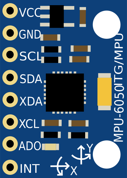
Pin Configuration and Descriptions
The MPU-6050 module typically has 8 pins. Below is the pinout description:
| Pin | Name | Description |
|---|---|---|
| 1 | VCC | Power supply input (3.3V to 5V). |
| 2 | GND | Ground connection. |
| 3 | SCL | I2C clock line. Connect to the SCL pin of the microcontroller. |
| 4 | SDA | I2C data line. Connect to the SDA pin of the microcontroller. |
| 5 | XDA | Auxiliary I2C data line (used for connecting additional sensors, optional). |
| 6 | XCL | Auxiliary I2C clock line (used for connecting additional sensors, optional). |
| 7 | AD0 | I2C address selector. Connect to GND for address 0x68 or VCC for address 0x69. |
| 8 | INT | Interrupt pin. Outputs a signal when data is ready or an event occurs. |
Usage Instructions
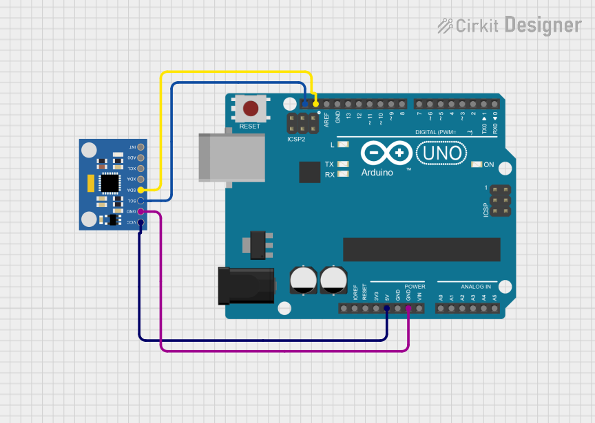
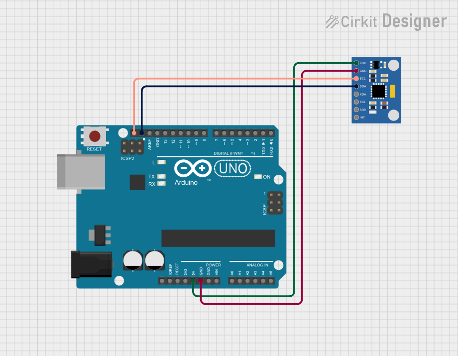
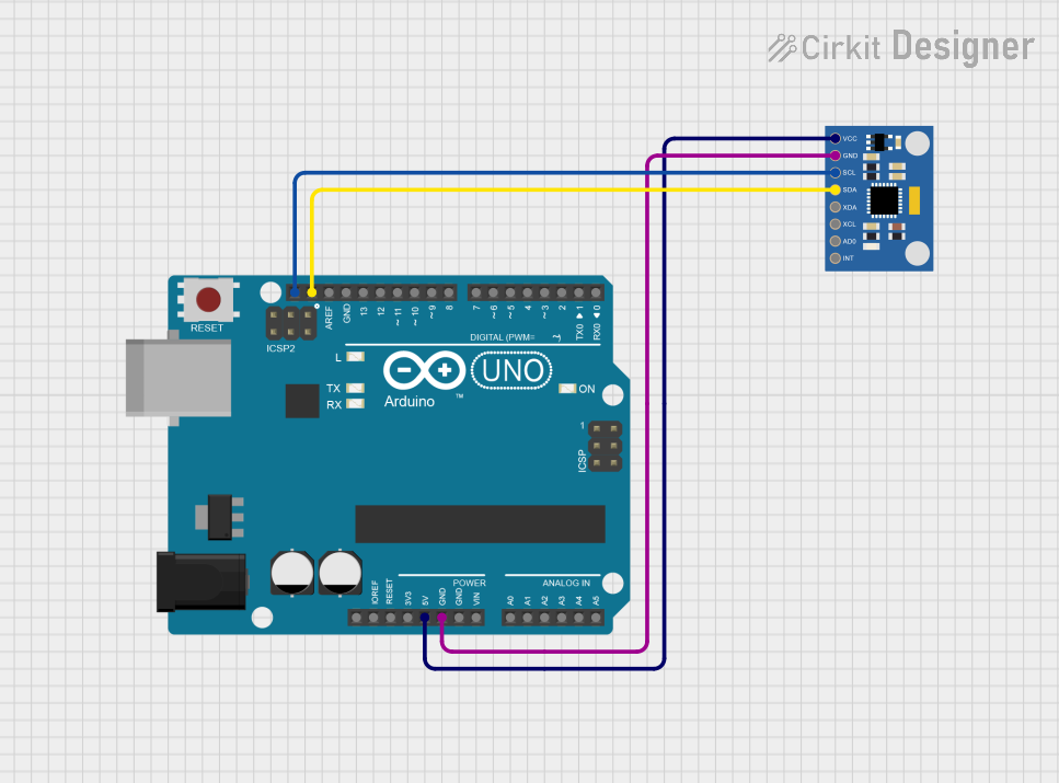
How to Use the MPU-6050 in a Circuit
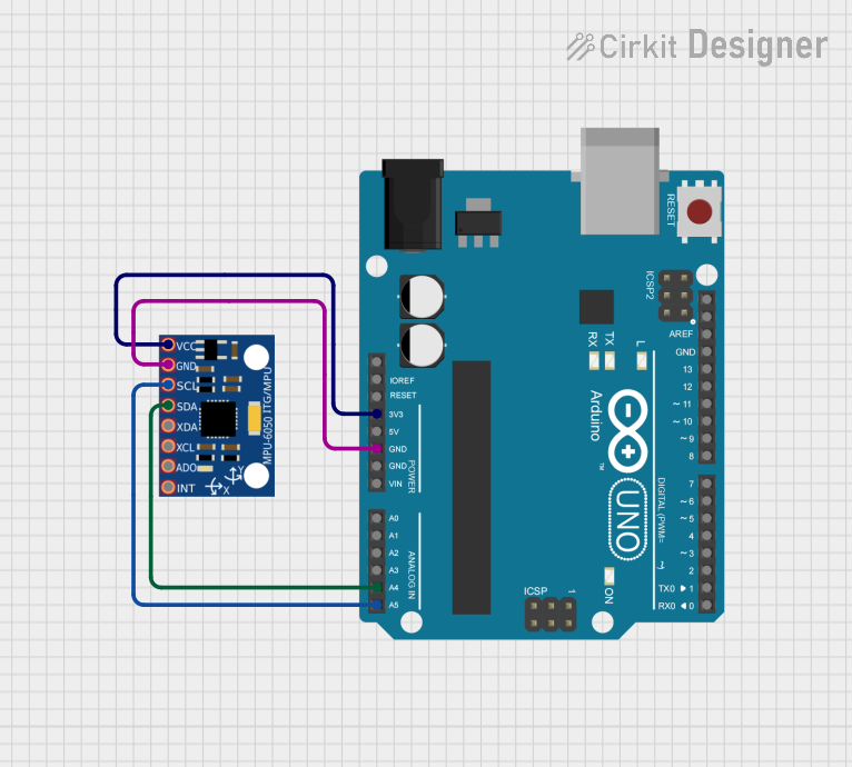
- Power the Sensor: Connect the VCC pin to a 3.3V or 5V power source and the GND pin to ground.
- Connect I2C Lines: Connect the SCL and SDA pins to the corresponding I2C pins on your microcontroller (e.g., A5 and A4 on an Arduino UNO).
- Set the I2C Address: Use the AD0 pin to select the I2C address (0x68 or 0x69). For most applications, connect AD0 to GND for the default address (0x68).
- Optional Connections: If needed, connect the INT pin to a digital input pin on your microcontroller to handle interrupts.
- Install Required Libraries: For Arduino, install the "MPU6050" or "Adafruit MPU6050" library via the Arduino Library Manager.
Important Considerations and Best Practices
- Use pull-up resistors (typically 4.7kΩ) on the SDA and SCL lines if they are not already present on the module.
- Avoid excessive noise on the power supply lines to ensure accurate readings.
- Calibrate the sensor before use to improve accuracy.
- Place the sensor on a stable surface to minimize vibrations during operation.
Example Code for Arduino UNO
Below is an example code to read accelerometer and gyroscope data from the MPU-6050 using the Arduino IDE:
#include <Wire.h>
#include <MPU6050.h>

// Create an MPU6050 object
MPU6050 mpu;

void setup() {
  Serial.begin(9600); // Initialize serial communication at 9600 baud
  Wire.begin();       // Initialize I2C communication

  // Initialize the MPU-6050
  if (!mpu.begin(MPU6050_SCALE_2000DPS, MPU6050_RANGE_2G)) {
    Serial.println("Could not find a valid MPU6050 sensor, check connections!");
    while (1); // Halt the program if the sensor is not detected
  }

  Serial.println("MPU6050 initialized successfully!");
}

void loop() {
  // Read accelerometer and gyroscope data
  Vector rawAccel = mpu.readRawAccel();
  Vector rawGyro = mpu.readRawGyro();

  // Print accelerometer data
  Serial.print("Accel X: "); Serial.print(rawAccel.XAxis);
  Serial.print(" | Y: "); Serial.print(rawAccel.YAxis);
  Serial.print(" | Z: "); Serial.println(rawAccel.ZAxis);

  // Print gyroscope data
  Serial.print("Gyro X: "); Serial.print(rawGyro.XAxis);
  Serial.print(" | Y: "); Serial.print(rawGyro.YAxis);
  Serial.print(" | Z: "); Serial.println(rawGyro.ZAxis);

  delay(500); // Wait for 500ms before the next reading
}
Troubleshooting and FAQs
Common Issues and Solutions
Sensor Not Detected
- Cause: Incorrect wiring or I2C address mismatch.
- Solution: Verify the connections and ensure the AD0 pin is set correctly for the desired I2C address.
Inaccurate Readings
- Cause: Lack of calibration or excessive vibrations.
- Solution: Perform sensor calibration and ensure the sensor is mounted on a stable surface.
No Data Output
- Cause: Missing pull-up resistors on the I2C lines.
- Solution: Add 4.7kΩ pull-up resistors to the SDA and SCL lines if not already present.
Interrupt Pin Not Working
- Cause: Interrupts not configured in the code.
- Solution: Ensure the interrupt pin is connected and properly configured in the software.
FAQs
Q: Can the MPU-6050 be powered with 5V?
- A: Yes, the module typically includes a voltage regulator, allowing it to be powered with 3.3V or 5V.
Q: How do I calibrate the MPU-6050?
- A: Use a calibration script or library to determine and compensate for sensor offsets.
Q: Can I connect multiple MPU-6050 sensors to the same I2C bus?
- A: Yes, but each sensor must have a unique I2C address. Use the AD0 pin to set different addresses.
Q: What is the maximum I2C speed supported by the MPU-6050?
- A: The MPU-6050 supports I2C speeds up to 400kHz (Fast Mode).