Cirkit Designer Logo
Cirkit Designer
Your all-in-one circuit design IDE
Home / 
Component Documentation

How to Use Key Studo photorésistant: Examples, Pinouts, and Specs

Image of Key Studo photorésistant
Cirkit Designer LogoDesign with Key Studo photorésistant in Cirkit Designer

Introduction

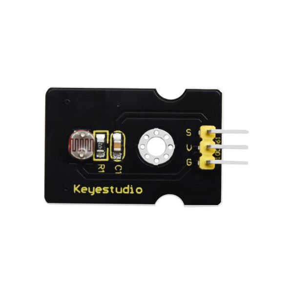
The Key Studio Photoresistor is a light-sensitive resistor, also known as a Light Dependent Resistor (LDR). Its resistance decreases as the intensity of light falling on it increases, making it an ideal component for light detection and control applications. This component is widely used in projects such as automatic lighting systems, light meters, and DIY electronics.

Explore Projects Built with Key Studo photorésistant

Use Cirkit Designer to design, explore, and prototype these projects online. Some projects support real-time simulation. Click "Open Project" to start designing instantly!
Arduino-Controlled Servo with Light Sensing
Image of Servo: A project utilizing Key Studo photorésistant in a practical application
This circuit features an Arduino UNO microcontroller interfaced with two photocells (LDRs) and a servo motor. The photocells are connected to analog inputs A0 and A1, and their average light intensity reading is used to control the position of the servo motor connected to digital pin D9. The circuit is powered by a pair of 18650 Li-ion batteries, which are also connected to a TP4056 charging module that can be charged via a solar cell, providing a renewable energy source for the system.
Cirkit Designer LogoOpen Project in Cirkit Designer
Solar-Powered LED Light with Battery Charging and Light Sensing
Image of ebt: A project utilizing Key Studo photorésistant in a practical application
This circuit is a solar-powered battery charging and LED lighting system. The solar cell charges a 18650 Li-ion battery through a TP4056 charging module, which also powers a 7805 voltage regulator to provide a stable 5V output. A photocell and MOSFET control the power to a high-power LED, allowing it to turn on or off based on ambient light conditions.
Cirkit Designer LogoOpen Project in Cirkit Designer
ESP32-Controlled Security System with RFID, PIR, and Laser Modules
Image of CPE doorlock system upgrade2: A project utilizing Key Studo photorésistant in a practical application
This is a security or access control system featuring laser-based detection, motion sensing, RFID scanning, and user input via a keypad. It is managed by an ESP32 microcontroller and includes visual and auditory feedback through LEDs and a buzzer, with an Electric Lock for physical access control. The system is powered by solar energy with battery backup and centralized power supply, ensuring continuous operation.
Cirkit Designer LogoOpen Project in Cirkit Designer
Arduino Nano-Controlled Lighting System with Gesture and Sound Interaction
Image of 4 load controll using hand gesture and sound controll: A project utilizing Key Studo photorésistant in a practical application
This circuit features an Arduino Nano microcontroller interfaced with an APDS-9960 RGB and Gesture Sensor for color and gesture detection, and a KY-038 microphone module for sound detection. The Arduino controls a 4-channel relay module, which in turn switches four AC bulbs on and off. The 12V power supply is used to power the relay module, and the bulbs are connected to the normally open (N.O.) contacts of the relays, allowing the Arduino to control the lighting based on sensor inputs.
Cirkit Designer LogoOpen Project in Cirkit Designer

Explore Projects Built with Key Studo photorésistant

Use Cirkit Designer to design, explore, and prototype these projects online. Some projects support real-time simulation. Click "Open Project" to start designing instantly!
Image of Servo: A project utilizing Key Studo photorésistant in a practical application
Arduino-Controlled Servo with Light Sensing
This circuit features an Arduino UNO microcontroller interfaced with two photocells (LDRs) and a servo motor. The photocells are connected to analog inputs A0 and A1, and their average light intensity reading is used to control the position of the servo motor connected to digital pin D9. The circuit is powered by a pair of 18650 Li-ion batteries, which are also connected to a TP4056 charging module that can be charged via a solar cell, providing a renewable energy source for the system.
Cirkit Designer LogoOpen Project in Cirkit Designer
Image of ebt: A project utilizing Key Studo photorésistant in a practical application
Solar-Powered LED Light with Battery Charging and Light Sensing
This circuit is a solar-powered battery charging and LED lighting system. The solar cell charges a 18650 Li-ion battery through a TP4056 charging module, which also powers a 7805 voltage regulator to provide a stable 5V output. A photocell and MOSFET control the power to a high-power LED, allowing it to turn on or off based on ambient light conditions.
Cirkit Designer LogoOpen Project in Cirkit Designer
Image of CPE doorlock system upgrade2: A project utilizing Key Studo photorésistant in a practical application
ESP32-Controlled Security System with RFID, PIR, and Laser Modules
This is a security or access control system featuring laser-based detection, motion sensing, RFID scanning, and user input via a keypad. It is managed by an ESP32 microcontroller and includes visual and auditory feedback through LEDs and a buzzer, with an Electric Lock for physical access control. The system is powered by solar energy with battery backup and centralized power supply, ensuring continuous operation.
Cirkit Designer LogoOpen Project in Cirkit Designer
Image of 4 load controll using hand gesture and sound controll: A project utilizing Key Studo photorésistant in a practical application
Arduino Nano-Controlled Lighting System with Gesture and Sound Interaction
This circuit features an Arduino Nano microcontroller interfaced with an APDS-9960 RGB and Gesture Sensor for color and gesture detection, and a KY-038 microphone module for sound detection. The Arduino controls a 4-channel relay module, which in turn switches four AC bulbs on and off. The 12V power supply is used to power the relay module, and the bulbs are connected to the normally open (N.O.) contacts of the relays, allowing the Arduino to control the lighting based on sensor inputs.
Cirkit Designer LogoOpen Project in Cirkit Designer

Common Applications and Use Cases

  • Automatic streetlights
  • Light intensity measurement
  • Solar trackers
  • DIY electronics projects
  • Light-sensitive alarms

Technical Specifications

The following table outlines the key technical details of the Key Studio Photoresistor:

Parameter Value
Manufacturer Key Studio
Manufacturer Part ID Key Studio
Resistance (Dark) 1 MΩ (approx.)
Resistance (Bright) 10 kΩ to 20 kΩ (approx.)
Operating Voltage 3.3V to 5V
Power Rating 100 mW
Response Time Rise: 20 ms, Fall: 30 ms
Operating Temperature -30°C to +70°C
Material Cadmium Sulfide (CdS)

Pin Configuration and Descriptions

The Key Studio Photoresistor is a two-terminal device. Below is the pin configuration:

Pin Description
Pin 1 Connects to the positive side of the circuit (VCC)
Pin 2 Connects to the negative side or ground (GND)

Usage Instructions

How to Use the Component in a Circuit

  1. Basic Circuit Setup:

    • Connect one terminal of the photoresistor to the positive voltage supply (VCC).
    • Connect the other terminal to a pull-down resistor (e.g., 10 kΩ) and then to ground (GND).
    • The junction between the photoresistor and the pull-down resistor serves as the output voltage point, which can be connected to an analog input pin of a microcontroller (e.g., Arduino).
  2. Voltage Divider Principle:

    • The photoresistor and the pull-down resistor form a voltage divider. The output voltage varies with the light intensity, which can be read by an analog-to-digital converter (ADC) on a microcontroller.

Important Considerations and Best Practices

  • Avoid Overheating: Ensure the photoresistor does not exceed its power rating of 100 mW to prevent damage.
  • Light Sensitivity: The response of the photoresistor may vary depending on the wavelength of light. Use it in environments with consistent light sources for accurate readings.
  • Pull-Down Resistor Value: Choose an appropriate pull-down resistor value (typically 10 kΩ) to balance sensitivity and response time.
  • Noise Reduction: Add a capacitor (e.g., 0.1 µF) across the photoresistor to filter out noise in the signal.

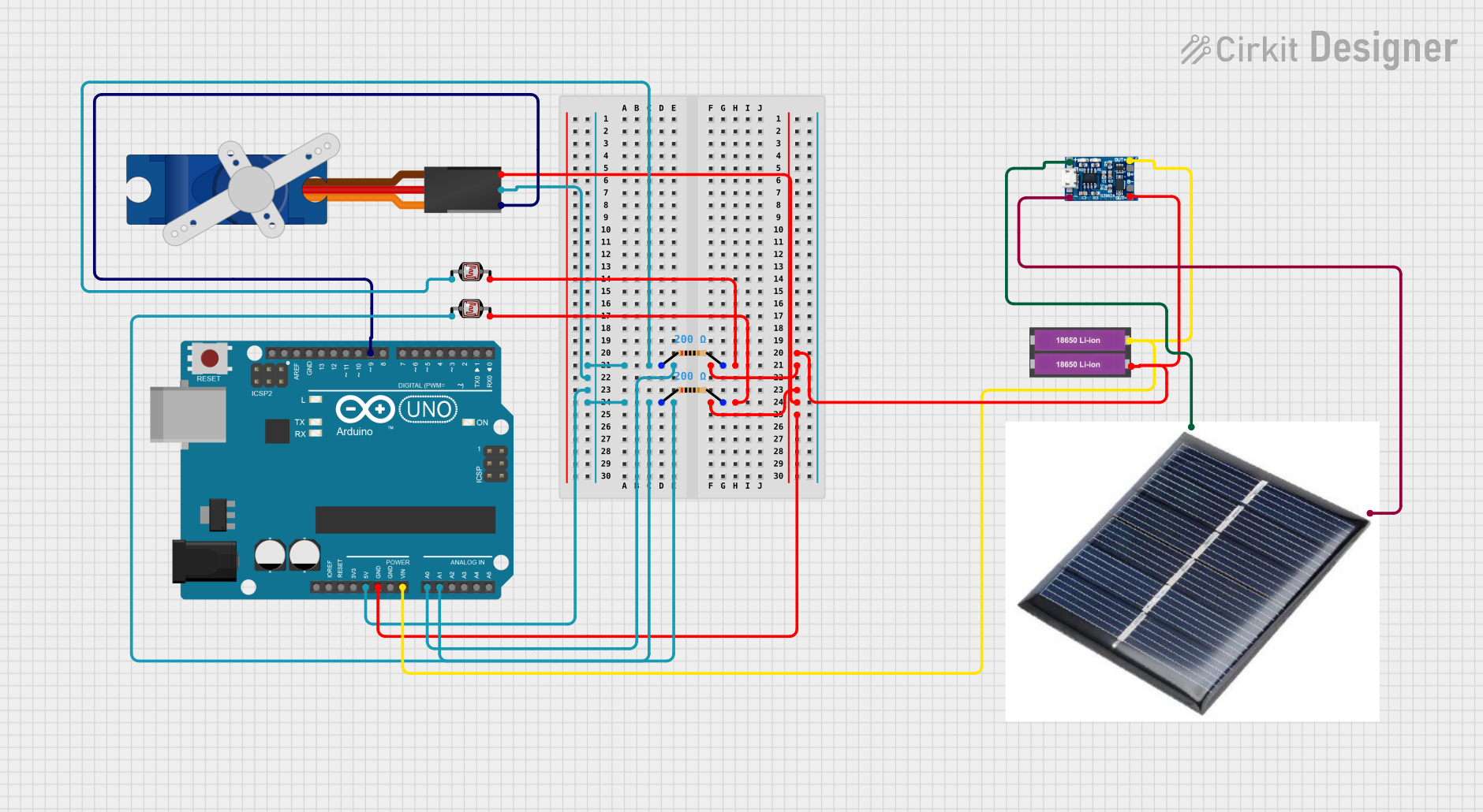
Example: Using the Photoresistor with Arduino UNO

Below is an example of how to use the Key Studio Photoresistor with an Arduino UNO to measure light intensity:

// Key Studio Photoresistor Example with Arduino UNO
// Reads light intensity and displays the value on the Serial Monitor

const int photoResistorPin = A0; // Analog pin connected to the photoresistor
int lightValue = 0;             // Variable to store the light intensity value

void setup() {
  Serial.begin(9600); // Initialize serial communication at 9600 baud
}

void loop() {
  lightValue = analogRead(photoResistorPin); // Read the analog value
  Serial.print("Light Intensity: ");         // Print label
  Serial.println(lightValue);               // Print the light intensity value
  delay(500);                               // Wait for 500 ms before next reading
}

Notes:

  • Connect the photoresistor to analog pin A0 on the Arduino UNO.
  • Use a 10 kΩ pull-down resistor in the voltage divider circuit.
  • The lightValue will range from 0 to 1023, corresponding to the light intensity.

Troubleshooting and FAQs

Common Issues and Solutions

  1. No Change in Output Voltage:

    • Cause: Incorrect wiring or damaged photoresistor.
    • Solution: Double-check the circuit connections and ensure the photoresistor is functional.
  2. Inconsistent Readings:

    • Cause: Electrical noise or unstable light source.
    • Solution: Add a capacitor across the photoresistor to filter noise and use a stable light source.
  3. Low Sensitivity:

    • Cause: Incorrect pull-down resistor value.
    • Solution: Experiment with different resistor values (e.g., 5 kΩ to 20 kΩ) to optimize sensitivity.
  4. Overheating:

    • Cause: Exceeding the power rating of the photoresistor.
    • Solution: Ensure the voltage and current through the photoresistor are within safe limits.

FAQs

Q1: Can the photoresistor detect infrared light?
A1: The Key Studio Photoresistor is most sensitive to visible light. It may have limited sensitivity to infrared light depending on the wavelength.

Q2: What is the maximum distance for light detection?
A2: The detection distance depends on the intensity of the light source. Brighter light sources can be detected from greater distances.

Q3: Can I use the photoresistor in outdoor applications?
A3: Yes, but ensure it is protected from extreme weather conditions and direct exposure to moisture.

Q4: How do I calibrate the photoresistor for specific light levels?
A4: Use the analog readings from the photoresistor to determine threshold values for your application, and adjust the pull-down resistor if needed.