Cirkit Designer Logo
Cirkit Designer
Your all-in-one circuit design IDE
Home / 
Component Documentation

How to Use terminalblock-04-01: Examples, Pinouts, and Specs

Image of terminalblock-04-01
Cirkit Designer LogoDesign with terminalblock-04-01 in Cirkit Designer

Introduction

A terminal block, also known as a terminal connector or connection block, is a modular block with an insulated frame that secures two or more wires together. The TerminalBlock-04-01 is a specific model of terminal block that is designed to facilitate easy wiring connections in a variety of electronic and electrical systems. This component is commonly used in industrial control systems, power supply units, consumer electronics, and DIY projects, including those involving Arduino boards.

Explore Projects Built with terminalblock-04-01

Use Cirkit Designer to design, explore, and prototype these projects online. Some projects support real-time simulation. Click "Open Project" to start designing instantly!
Modular Power Distribution System with Multiple SMPS Units and 120V Outlet
Image of Cellion-Tesla: A project utilizing terminalblock-04-01 in a practical application
This circuit is designed to convert 240V AC power to both 12V and 24V DC outputs using multiple SMPS units. Terminal blocks are used to organize and distribute the power, while a 120V outlet provides additional AC power access. The circuit is likely used for powering various electronic devices that require different voltage levels.
Cirkit Designer LogoOpen Project in Cirkit Designer
Peltier-Controlled Thermal Management System with SPST Switch
Image of Mini car refrigerator circuit: A project utilizing terminalblock-04-01 in a practical application
This circuit consists of multiple Peltier modules and fans connected in parallel to a digital power supply, with a rocker switch (SPST) controlling the power flow to one of the Peltier modules and multiple fans. The 2.1mm Barrel Jack with Terminal Block serves as the power input connector, and the rocker switch allows for selective enabling or disabling of the connected devices. The circuit is designed to provide cooling or heating through the Peltier modules while the fans assist in heat dissipation or air circulation.
Cirkit Designer LogoOpen Project in Cirkit Designer
Battery-Powered Relay Control System with Directional Switch
Image of Skema Lampu D2: A project utilizing terminalblock-04-01 in a practical application
This circuit involves a 12V battery powering a relay system controlled by a directional switch. The relays are connected through terminal blocks and are used to switch between different outputs, indicated by the AdaGator Top components.
Cirkit Designer LogoOpen Project in Cirkit Designer
Mega2560-Controlled Automation System with Non-Contact Liquid Level Sensing and Motor Control
Image of Project_AutomaticBartender: A project utilizing terminalblock-04-01 in a practical application
This circuit appears to be a complex control system centered around an Arduino Mega2560 R3 Pro microcontroller, which interfaces with multiple sensors (XKC-Y26-V non-contact liquid level sensors and an LM35 temperature sensor), servo motors, a touch display, and an IBT-2 H-Bridge motor driver for controlling a planetary gearbox motor. The system also includes a UART TTL to RS485 converter for communication, likely with the touch display, and a power management subsystem with a switching power supply, fuses, and circuit breakers for safety and voltage regulation (XL4016). The absence of embedded code suggests that the functionality of the microcontroller is not defined within the provided data.
Cirkit Designer LogoOpen Project in Cirkit Designer

Explore Projects Built with terminalblock-04-01

Use Cirkit Designer to design, explore, and prototype these projects online. Some projects support real-time simulation. Click "Open Project" to start designing instantly!
Image of Cellion-Tesla: A project utilizing terminalblock-04-01 in a practical application
Modular Power Distribution System with Multiple SMPS Units and 120V Outlet
This circuit is designed to convert 240V AC power to both 12V and 24V DC outputs using multiple SMPS units. Terminal blocks are used to organize and distribute the power, while a 120V outlet provides additional AC power access. The circuit is likely used for powering various electronic devices that require different voltage levels.
Cirkit Designer LogoOpen Project in Cirkit Designer
Image of Mini car refrigerator circuit: A project utilizing terminalblock-04-01 in a practical application
Peltier-Controlled Thermal Management System with SPST Switch
This circuit consists of multiple Peltier modules and fans connected in parallel to a digital power supply, with a rocker switch (SPST) controlling the power flow to one of the Peltier modules and multiple fans. The 2.1mm Barrel Jack with Terminal Block serves as the power input connector, and the rocker switch allows for selective enabling or disabling of the connected devices. The circuit is designed to provide cooling or heating through the Peltier modules while the fans assist in heat dissipation or air circulation.
Cirkit Designer LogoOpen Project in Cirkit Designer
Image of Skema Lampu D2: A project utilizing terminalblock-04-01 in a practical application
Battery-Powered Relay Control System with Directional Switch
This circuit involves a 12V battery powering a relay system controlled by a directional switch. The relays are connected through terminal blocks and are used to switch between different outputs, indicated by the AdaGator Top components.
Cirkit Designer LogoOpen Project in Cirkit Designer
Image of Project_AutomaticBartender: A project utilizing terminalblock-04-01 in a practical application
Mega2560-Controlled Automation System with Non-Contact Liquid Level Sensing and Motor Control
This circuit appears to be a complex control system centered around an Arduino Mega2560 R3 Pro microcontroller, which interfaces with multiple sensors (XKC-Y26-V non-contact liquid level sensors and an LM35 temperature sensor), servo motors, a touch display, and an IBT-2 H-Bridge motor driver for controlling a planetary gearbox motor. The system also includes a UART TTL to RS485 converter for communication, likely with the touch display, and a power management subsystem with a switching power supply, fuses, and circuit breakers for safety and voltage regulation (XL4016). The absence of embedded code suggests that the functionality of the microcontroller is not defined within the provided data.
Cirkit Designer LogoOpen Project in Cirkit Designer

Technical Specifications

General Specifications

  • Type: Screw-type terminal block
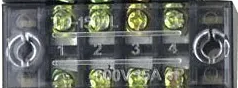
  • Number of Positions: 4
  • Pitch: 5.08mm
  • Wire Gauge Range: 26-16 AWG
  • Rated Voltage: 300V
  • Rated Current: 16A
  • Withstanding Voltage: 2000V AC/minute
  • Operating Temperature Range: -40°C to +105°C
  • Material: Polyamide 66, UL94V-0 flame retardant
  • Terminal Material: Brass, Nickel plated
  • Screw Material: Steel, Zinc plated

Pin Configuration and Descriptions

Pin Number Description
1 Wire connection 1
2 Wire connection 2
3 Wire connection 3
4 Wire connection 4

Each pin corresponds to a separate wire connection point within the terminal block. The screws on the terminal block can be tightened or loosened to secure or release the wire.

Usage Instructions

Wiring the Terminal Block

  1. Strip the Wire: Strip approximately 5-7mm of insulation from the end of each wire that will be inserted into the terminal block.
  2. Insert the Wire: Loosen the screws on the terminal block and insert the stripped end of the wire into the corresponding hole.
  3. Secure the Wire: Tighten the screw to ensure a secure and reliable electrical connection. Do not over-tighten as this may damage the wire or the terminal block.
  4. Repeat for Other Wires: Repeat the process for each wire, ensuring that each one is securely connected to its respective position in the terminal block.

Best Practices

  • Ensure that the power is turned off before making connections to the terminal block.
  • Use wires that are within the specified gauge range to ensure a secure fit and reliable connection.
  • Periodically check the connections for any signs of corrosion or loosening.
  • Do not exceed the voltage and current ratings to prevent damage or potential hazards.

Troubleshooting and FAQs

Common Issues

  • Loose Connections: If a wire is not securely fastened, it may cause intermittent connections or power loss. Tighten the screw to secure the wire.
  • Stripped Screws: Over-tightening can strip the screws, making it difficult to secure the wires. If this happens, the terminal block may need to be replaced.
  • Overheating: If the terminal block is overheating, it may be due to exceeding the current rating or a loose connection. Check the current load and connections.

FAQs

Q: Can I use this terminal block with an Arduino UNO? A: Yes, the TerminalBlock-04-01 can be used to make secure connections between the Arduino UNO and other components or external circuits.

Q: What should I do if the terminal block is not holding the wire securely? A: Ensure that the wire is stripped to the correct length and that the screw is tightened adequately. If the problem persists, check if the wire gauge is within the specified range.

Q: Is it possible to connect two wires to one terminal? A: While it is possible to connect two wires to one terminal, it is not recommended as it may not provide a secure connection. It is better to use one wire per terminal.

For Arduino UNO users, here is a simple example of how to connect an LED using the TerminalBlock-04-01:

// Define the Arduino pin connected to the LED through the terminal block
const int ledPin = 13;

void setup() {
  // Set the LED pin as an output
  pinMode(ledPin, OUTPUT);
}

void loop() {
  // Turn the LED on
  digitalWrite(ledPin, HIGH);
  delay(1000); // Wait for 1 second
  // Turn the LED off
  digitalWrite(ledPin, LOW);
  delay(1000); // Wait for 1 second
}

In this example, the anode of the LED would be connected to pin 13 of the Arduino UNO, and the cathode would be connected to the ground, both through the terminal block for a secure connection. Remember to include a current-limiting resistor in series with the LED to prevent damage.