Cirkit Designer Logo
Cirkit Designer
Your all-in-one circuit design IDE
Home / 
Component Documentation

How to Use Power Cell - LiPo Charger/Booster: Examples, Pinouts, and Specs

Image of Power Cell - LiPo Charger/Booster
Cirkit Designer LogoDesign with Power Cell - LiPo Charger/Booster in Cirkit Designer

Introduction

The Power Cell - LiPo Charger/Booster is a sophisticated electronic module designed to charge single-cell Lithium Polymer (LiPo) batteries and boost the output voltage to a higher, selectable level. This component is ideal for portable, wearable, and IoT devices where a stable power supply is crucial. It integrates a micro-USB port for charging and provides a convenient solution for powering projects that require a compact energy source.

Explore Projects Built with Power Cell - LiPo Charger/Booster

Use Cirkit Designer to design, explore, and prototype these projects online. Some projects support real-time simulation. Click "Open Project" to start designing instantly!
Battery-Powered 18650 Li-ion Charger with USB Output and Adjustable Voltage Regulator
Image of Breadboard: A project utilizing Power Cell - LiPo Charger/Booster in a practical application
This circuit is a battery management and power supply system that uses three 3.7V batteries connected to a 3S 10A Li-ion 18650 Charger Protection Board Module for balanced charging and protection. The system includes a TP4056 Battery Charging Protection Module for additional charging safety, a Step Up Boost Power Converter to regulate and boost the voltage, and a USB regulator to provide a stable 5V output, controlled by a push switch.
Cirkit Designer LogoOpen Project in Cirkit Designer
Battery-Powered Raspberry Pi 3B+ with TP4056 and DC/DC Booster
Image of raspberry power supply: A project utilizing Power Cell - LiPo Charger/Booster in a practical application
This circuit is a portable power supply system that charges a 18650 Li-ion battery using a TP4056 charging module and boosts the voltage to power a Raspberry Pi 3b+ via a DC/DC booster. The TP4056 module manages the charging of the battery, while the DC/DC booster converts the battery voltage to a stable 5V output for the Raspberry Pi.
Cirkit Designer LogoOpen Project in Cirkit Designer
Battery-Powered Lora G2 Node Station with 18650 Li-ion Batteries and Boost Converter
Image of Custom-Lora-G2-Node: A project utilizing Power Cell - LiPo Charger/Booster in a practical application
This circuit is a portable power supply system that uses multiple 18650 Li-ion batteries to provide a stable 5V output through a boost converter. It includes a fast charging module with a USB-C input for recharging the batteries and a battery indicator for monitoring the battery status. The system powers a Lora G2 Node Station, making it suitable for wireless communication applications.
Cirkit Designer LogoOpen Project in Cirkit Designer
Battery-Powered DC Motor Control with USB Charging and LED Indicator
Image of lumantas: A project utilizing Power Cell - LiPo Charger/Booster in a practical application
This circuit is designed to charge a Li-ion battery and power a DC motor and a 12V LED. The TP4056 module manages the battery charging process, while the PowerBoost 1000 and MT3608 boost converters step up the voltage to drive the motor and LED, respectively. Two rocker switches control the power flow to the LED and the charging circuit.
Cirkit Designer LogoOpen Project in Cirkit Designer

Explore Projects Built with Power Cell - LiPo Charger/Booster

Use Cirkit Designer to design, explore, and prototype these projects online. Some projects support real-time simulation. Click "Open Project" to start designing instantly!
Image of Breadboard: A project utilizing Power Cell - LiPo Charger/Booster in a practical application
Battery-Powered 18650 Li-ion Charger with USB Output and Adjustable Voltage Regulator
This circuit is a battery management and power supply system that uses three 3.7V batteries connected to a 3S 10A Li-ion 18650 Charger Protection Board Module for balanced charging and protection. The system includes a TP4056 Battery Charging Protection Module for additional charging safety, a Step Up Boost Power Converter to regulate and boost the voltage, and a USB regulator to provide a stable 5V output, controlled by a push switch.
Cirkit Designer LogoOpen Project in Cirkit Designer
Image of raspberry power supply: A project utilizing Power Cell - LiPo Charger/Booster in a practical application
Battery-Powered Raspberry Pi 3B+ with TP4056 and DC/DC Booster
This circuit is a portable power supply system that charges a 18650 Li-ion battery using a TP4056 charging module and boosts the voltage to power a Raspberry Pi 3b+ via a DC/DC booster. The TP4056 module manages the charging of the battery, while the DC/DC booster converts the battery voltage to a stable 5V output for the Raspberry Pi.
Cirkit Designer LogoOpen Project in Cirkit Designer
Image of Custom-Lora-G2-Node: A project utilizing Power Cell - LiPo Charger/Booster in a practical application
Battery-Powered Lora G2 Node Station with 18650 Li-ion Batteries and Boost Converter
This circuit is a portable power supply system that uses multiple 18650 Li-ion batteries to provide a stable 5V output through a boost converter. It includes a fast charging module with a USB-C input for recharging the batteries and a battery indicator for monitoring the battery status. The system powers a Lora G2 Node Station, making it suitable for wireless communication applications.
Cirkit Designer LogoOpen Project in Cirkit Designer
Image of lumantas: A project utilizing Power Cell - LiPo Charger/Booster in a practical application
Battery-Powered DC Motor Control with USB Charging and LED Indicator
This circuit is designed to charge a Li-ion battery and power a DC motor and a 12V LED. The TP4056 module manages the battery charging process, while the PowerBoost 1000 and MT3608 boost converters step up the voltage to drive the motor and LED, respectively. Two rocker switches control the power flow to the LED and the charging circuit.
Cirkit Designer LogoOpen Project in Cirkit Designer

Common Applications and Use Cases

  • Portable electronic devices
  • Wearable technology
  • IoT devices
  • DIY projects requiring a rechargeable power source
  • Robotics

Technical Specifications

Key Technical Details

  • Input Voltage (via micro-USB): 5V
  • Battery Charging Voltage: 4.2V (for single-cell LiPo batteries)
  • Selectable Output Voltages: Typically 3.3V and 5V
  • Maximum Charging Current: 1A (adjustable)
  • Output Current: Depends on the input and output voltage settings
  • Efficiency: Up to 95% (depends on input and output voltages)
  • Operating Temperature: -40°C to +85°C

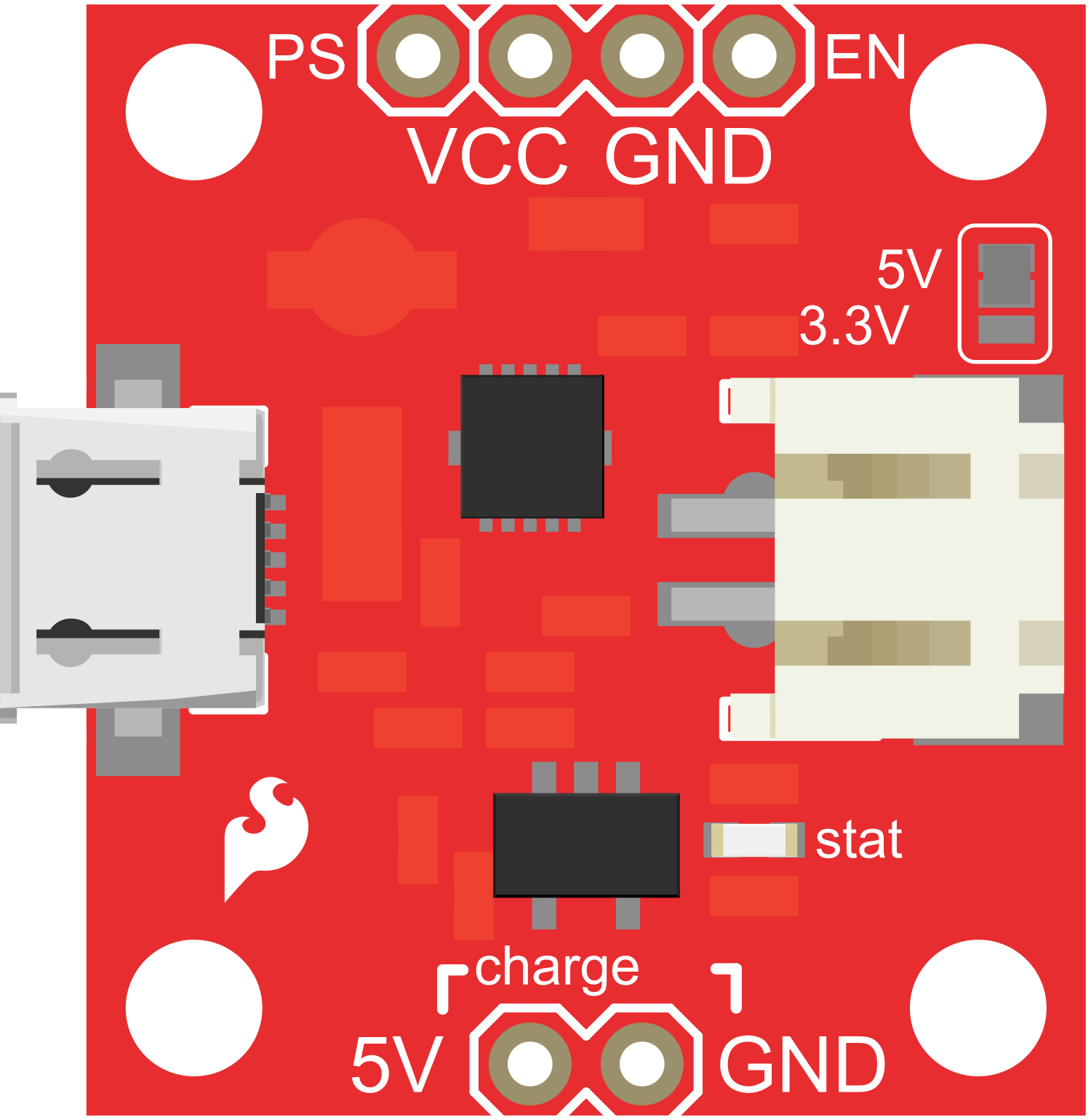
Pin Configuration and Descriptions

Pin Name Description
BAT+ Positive terminal for LiPo battery connection
BAT- Negative terminal for LiPo battery connection
GND Ground connection
VOUT Regulated output voltage
USB+ Positive input from micro-USB port
USB- Negative input from micro-USB port
EN Enable pin for the booster circuit (active high)
SEL Voltage selection pin (logic level determines output voltage)

Usage Instructions

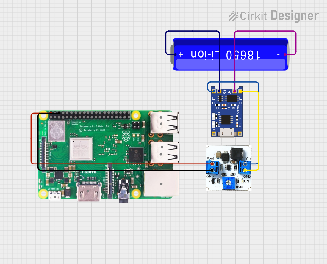
How to Use the Component in a Circuit

  1. Connecting the Battery:

    • Connect the LiPo battery to the BAT+ and BAT- terminals, ensuring correct polarity.
  2. Charging the Battery:

    • Plug a micro-USB cable into the module and a 5V USB power source.
    • The onboard charging circuit will safely charge the connected LiPo battery.
  3. Selecting Output Voltage:

    • Use the SEL pin to select the desired output voltage. A logic high will typically select 5V, and a logic low will select 3.3V.
  4. Enabling the Booster:

    • Apply a logic high signal to the EN pin to enable the booster circuit.
  5. Drawing Power:

    • Connect your load to the VOUT and GND pins, ensuring it does not exceed the module's maximum output current rating.

Important Considerations and Best Practices

  • Always verify the polarity of the LiPo battery before connecting it to the module.
  • Do not exceed the recommended charging current by adjusting the onboard potentiometer without proper knowledge.
  • Ensure the input power source does not exceed 5V to avoid damaging the module.
  • Avoid placing the module in environments that exceed its operating temperature range.
  • When selecting the output voltage, ensure that your load can tolerate the selected voltage.

Troubleshooting and FAQs

Common Issues

  • Battery Not Charging:

    • Check the micro-USB cable and power source.
    • Ensure the battery polarity is correct.
    • Verify that the battery is not damaged.
  • No Output Voltage:

    • Ensure the EN pin is set high to enable the booster.
    • Check if the SEL pin is correctly set for the desired output voltage.
    • Verify that the load does not exceed the maximum output current.

Solutions and Tips for Troubleshooting

  • If the battery is not charging, try a different USB cable or power source.
  • For no output voltage, double-check the connections to the EN and SEL pins.
  • If the module is overheating, reduce the load or improve ventilation around the module.

FAQs

Q: Can I charge multiple LiPo batteries at once? A: No, this module is designed to charge a single-cell LiPo battery.

Q: What should I do if the module gets hot during operation? A: Ensure that the load is within the module's limits and that there is adequate ventilation. If the issue persists, reduce the load.

Q: Can I use this module with batteries other than LiPo? A: This module is specifically designed for single-cell LiPo batteries and may not be suitable for other battery types.

Q: How do I adjust the charging current? A: The charging current can be adjusted via an onboard potentiometer, but this should only be done by those with the appropriate knowledge and experience.

Example Code for Arduino UNO

// Example code to enable the Power Cell - LiPo Charger/Booster with an Arduino UNO

const int enablePin = 7; // Connect to the EN pin on the module
const int selectPin = 8; // Connect to the SEL pin on the module

void setup() {
  pinMode(enablePin, OUTPUT);
  pinMode(selectPin, OUTPUT);

  // Enable the booster circuit
  digitalWrite(enablePin, HIGH);

  // Select output voltage (HIGH for 5V, LOW for 3.3V)
  digitalWrite(selectPin, HIGH); // Set this to LOW for 3.3V
}

void loop() {
  // Your code here to interact with the powered circuit
}

Remember to ensure that the Arduino pins used in the code are correctly connected to the EN and SEL pins on the Power Cell module. Adjust the selectPin logic level according to the required output voltage for your project.