How to Use PIR HC-SR501: Examples, Pinouts, and Specs
Introduction
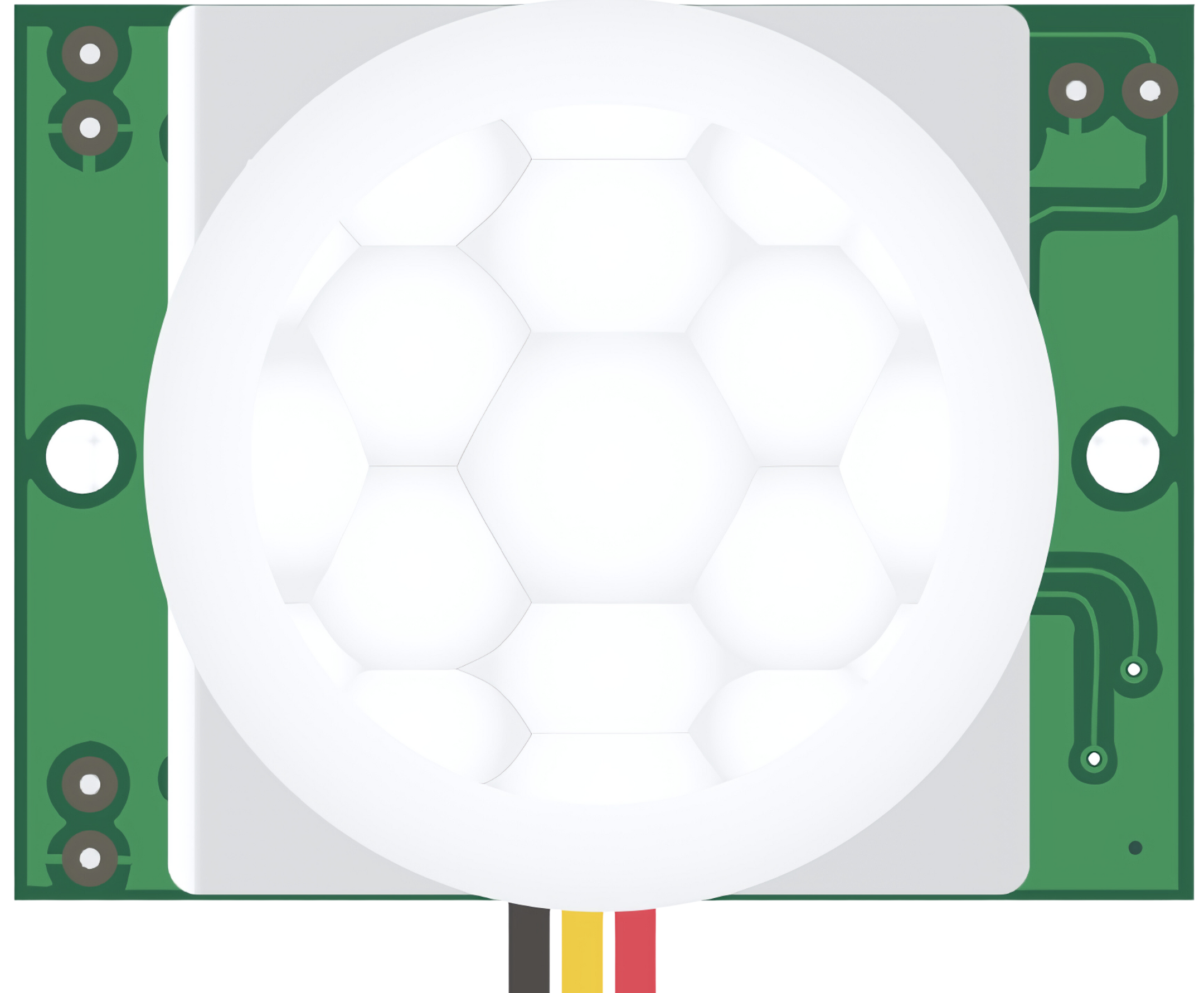
The PIR HC-SR501 is a Passive Infrared (PIR) sensor module designed to detect motion through changes in infrared levels emitted by objects in its field of view. It is widely used in security systems, lighting controls, and home automation projects due to its low cost, ease of use, and reliability.
Explore Projects Built with PIR HC-SR501
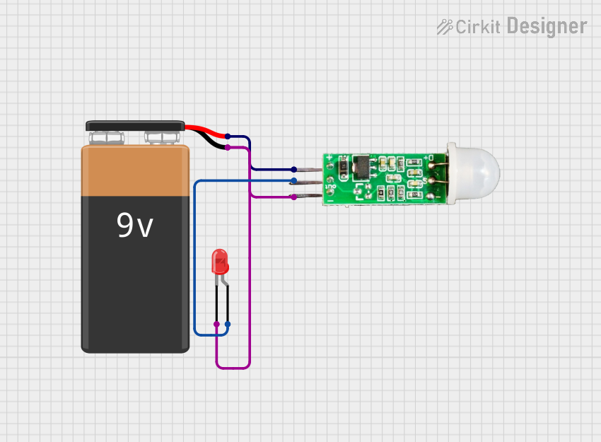
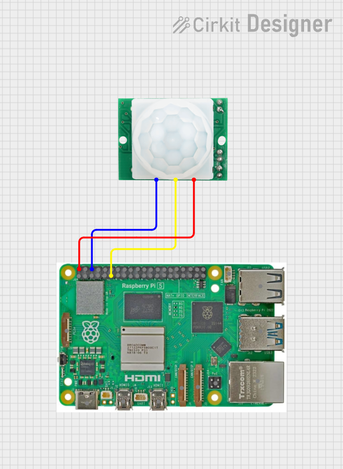
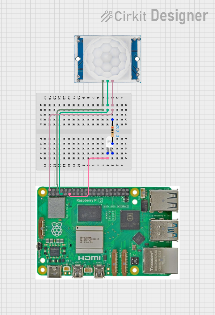
Explore Projects Built with PIR HC-SR501
Common Applications and Use Cases
- Motion-activated alarms
- Automatic lighting control
- Presence detection for energy-saving systems
- Robotics and interactive installations
Technical Specifications
Key Technical Details
- Voltage: 5V – 20V
- Current: 65mA (typical)
- Power Consumption: 0.15mW (static), 0.3mW (active)
- Detection Range: Up to 7 meters
- Detection Angle: < 120 degrees
- Delay Time: Adjustable from 0.3 seconds to 5 minutes
- Output Level: High 3.3V, Low 0V
- Operating Temperature: -20°C to +80°C
Pin Configuration and Descriptions
| Pin Name | Description |
|---|---|
| VCC | Power supply (5V – 20V) |
| OUT | Digital output signal (High/Low) |
| GND | Ground |
Usage Instructions
How to Use the Component in a Circuit
- Connect the VCC pin to a 5V power supply.
- Connect the GND pin to the ground of the power supply.
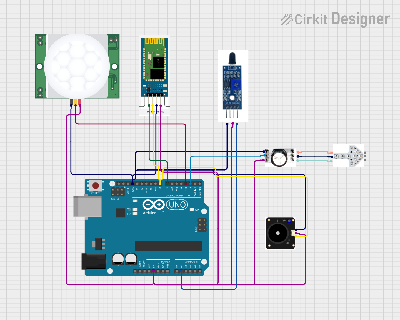
- Connect the OUT pin to a digital input pin on a microcontroller, such as an Arduino UNO.
Important Considerations and Best Practices
- Ensure that the power supply voltage does not exceed 20V.
- Avoid placing the sensor in an environment with rapid temperature changes to prevent false triggers.
- The sensor requires a warm-up time of approximately 20-60 seconds to calibrate to the infrared level of the environment.
- Adjust the delay time and sensitivity knobs on the sensor module to suit your application needs.
Example Arduino UNO Code
// Define the PIR motion sensor pin
const int PIRPin = 2; // Connect PIR sensor's OUT pin to Arduino's pin 2

void setup() {
  pinMode(PIRPin, INPUT); // Set the PIR pin as an input
  Serial.begin(9600);    // Initialize serial communication
}

void loop() {
  int motionStatus = digitalRead(PIRPin); // Read the PIR sensor's output

  if (motionStatus == HIGH) {
    // When motion is detected, print a message
    Serial.println("Motion detected!");
    // Add your code here to handle the motion detection event
  } else {
    // When no motion is detected, print a message
    Serial.println("No motion detected.");
  }

  delay(1000); // Wait for 1 second before reading again
}
Troubleshooting and FAQs
Common Issues Users Might Face
- False triggers: Adjust the sensitivity and delay time knobs to fine-tune the sensor's performance.
- No response: Check the power supply and connections to ensure the sensor is properly powered and connected.
- Intermittent operation: Ensure that the sensor is not facing a heat source or window where moving heat signatures can cause false triggers.
Solutions and Tips for Troubleshooting
- If the sensor is not responding, verify that the power supply is within the specified voltage range and that all connections are secure.
- In case of false triggers, try repositioning the sensor away from potential environmental interferences.
- Allow the sensor to warm up and calibrate upon initial power-up before testing its functionality.
FAQs
Q: Can the sensor detect motion through walls? A: No, the PIR sensor cannot detect motion through walls as it relies on detecting infrared radiation from objects.
Q: How can I adjust the range and sensitivity of the sensor? A: The HC-SR501 module typically has two potentiometers to adjust the delay time and sensitivity. Rotate these knobs to increase or decrease the respective settings.
Q: Is it possible to power the sensor with a 3.3V supply? A: The sensor is designed to operate with a supply voltage of 5V to 20V. Using a voltage lower than 5V may result in unreliable or non-functional operation.