How to Use 1channel 5V 30A relay: Examples, Pinouts, and Specs
Introduction
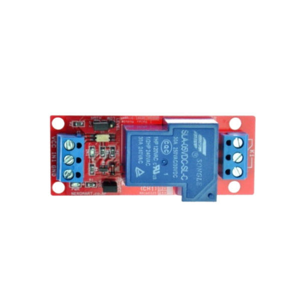
The NEROMART NER-13709 is a single-channel relay module designed to control high-power devices using low-power control signals. Operating at 5V, this relay can handle loads of up to 30A, making it ideal for switching high-current devices such as motors, heaters, lights, and other appliances. Its compact design and high current capacity make it a versatile component for home automation, industrial control systems, and DIY electronics projects.
Explore Projects Built with 1channel 5V 30A relay

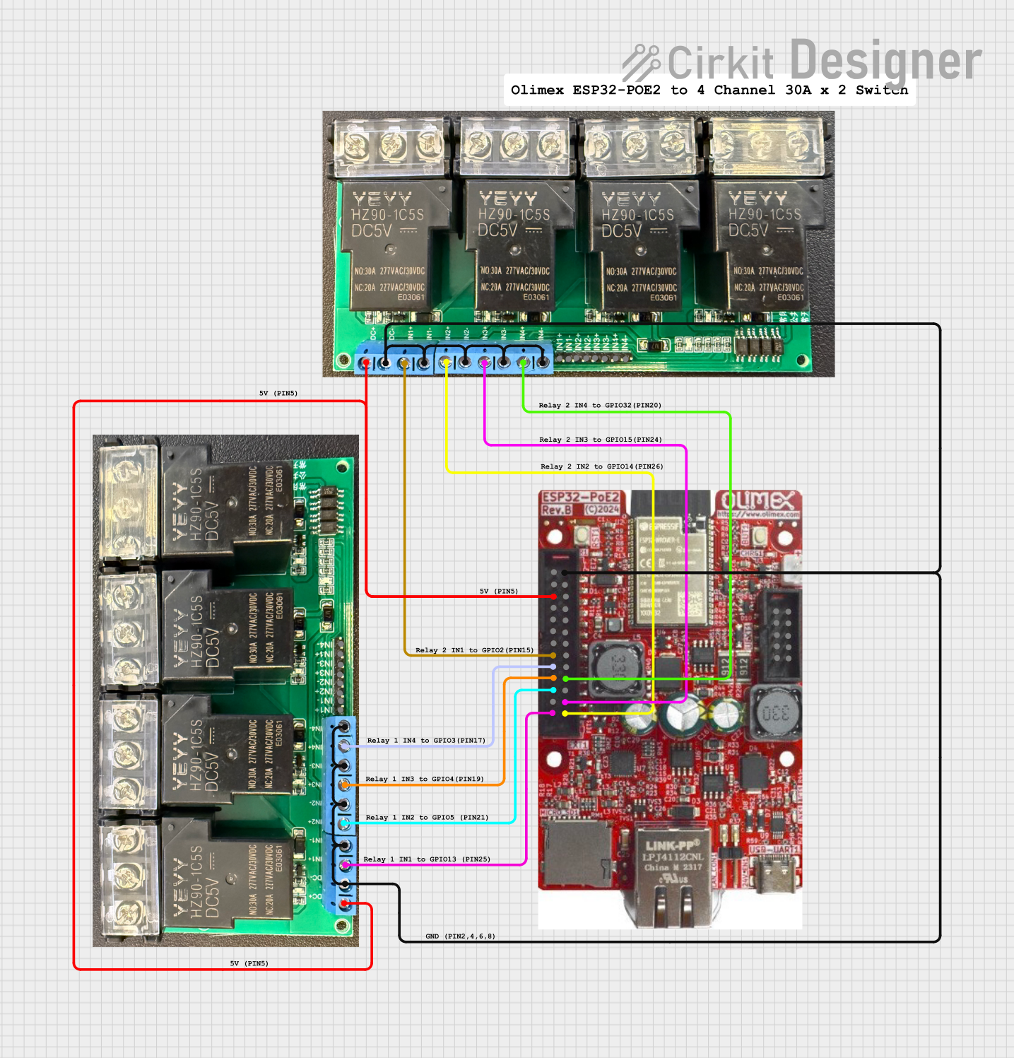
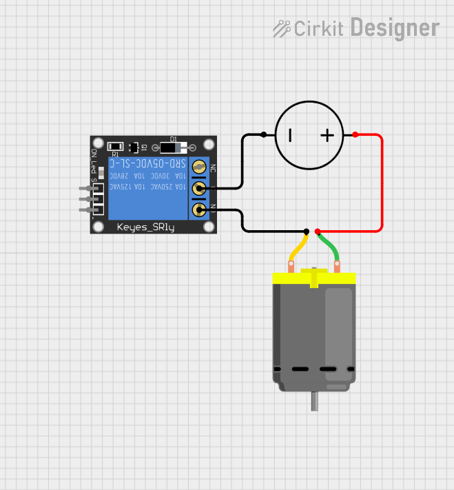

Explore Projects Built with 1channel 5V 30A relay
Common Applications
- Home automation (e.g., controlling lights, fans, or appliances)
- Industrial equipment control
- Motor and pump control
- DIY electronics and Arduino-based projects
- Smart home systems
Technical Specifications
Below are the key technical details of the NEROMART NER-13709 relay module:
| Parameter | Specification |
|---|---|
| Operating Voltage | 5V DC |
| Maximum Load Current | 30A |
| Maximum Load Voltage | 250V AC / 30V DC |
| Control Signal Voltage | 3.3V to 5V DC |
| Relay Type | SPDT (Single Pole Double Throw) |
| Dimensions | 50mm x 26mm x 18mm |
| Isolation | Optocoupler isolation for safety |
| Trigger Type | Active Low |
| Operating Temperature | -40°C to 85°C |
Pin Configuration
The relay module has 6 pins and terminals, as described in the table below:
| Pin/Terminal | Description |
|---|---|
| VCC | Connect to the 5V power supply. |
| GND | Connect to the ground of the power supply. |
| IN | Control signal input (active low). Connect to a microcontroller or control pin. |
| COM | Common terminal for the relay switch. |
| NO | Normally Open terminal. Connect the load here if it should be off by default. |
| NC | Normally Closed terminal. Connect the load here if it should be on by default. |
Usage Instructions
How to Use the Relay in a Circuit
- Power the Relay Module: Connect the VCC pin to a 5V DC power supply and the GND pin to the ground.
- Control Signal: Connect the IN pin to a microcontroller (e.g., Arduino) or a control circuit. The relay is triggered when the IN pin receives a LOW signal.
- Load Connection:
- Connect the load's live wire to the COM terminal.
- Use the NO terminal if the load should be off by default and turn on when the relay is triggered.
- Use the NC terminal if the load should be on by default and turn off when the relay is triggered.
- Isolation: Ensure proper electrical isolation between the control circuit and the high-power load to prevent damage or hazards.
Important Considerations
- Power Supply: Ensure the relay module is powered with a stable 5V DC supply.
- Load Ratings: Do not exceed the maximum load current (30A) or voltage (250V AC / 30V DC).
- Heat Dissipation: For high-current loads, ensure proper ventilation or heat dissipation to prevent overheating.
- Safety: Always disconnect power before wiring the relay to avoid electric shock.
Example: Using the Relay with an Arduino UNO
Below is an example of how to control the relay using an Arduino UNO:
// Example: Controlling a 1-Channel 5V 30A Relay with Arduino UNO
// Manufacturer: NEROMART
// Part ID: NER-13709

const int relayPin = 7; // Pin connected to the relay module's IN pin

void setup() {
  pinMode(relayPin, OUTPUT); // Set the relay pin as an output
  digitalWrite(relayPin, HIGH); // Ensure the relay is off initially
}

void loop() {
  digitalWrite(relayPin, LOW); // Turn the relay ON (active low)
  delay(5000); // Keep the relay on for 5 seconds
  digitalWrite(relayPin, HIGH); // Turn the relay OFF
  delay(5000); // Keep the relay off for 5 seconds
}
Notes:
- The relay is active low, meaning it turns on when the control signal is LOW.
- Use an external power supply if the relay draws more current than the Arduino can provide.
Troubleshooting and FAQs
Common Issues and Solutions
Relay Not Switching
- Cause: Insufficient control signal voltage or current.
- Solution: Ensure the IN pin receives a proper LOW signal (below 0.8V) to activate the relay.
Load Not Turning On/Off
- Cause: Incorrect wiring of the load to the relay terminals.
- Solution: Double-check the connections to the COM, NO, and NC terminals.
Overheating
- Cause: Exceeding the relay's maximum current rating.
- Solution: Ensure the load does not exceed 30A. Use a heat sink or cooling fan if necessary.
Arduino Resets When Relay Activates
- Cause: Voltage spikes or insufficient power supply.
- Solution: Add a flyback diode across the relay coil and use a decoupling capacitor near the Arduino's power pins.
FAQs
Can I use this relay with a 3.3V microcontroller?
- Yes, the relay can be triggered with a 3.3V control signal, but ensure the VCC pin is powered with 5V.
Is the relay safe for inductive loads like motors?
- Yes, but you should use a flyback diode or snubber circuit to protect the relay from voltage spikes.
Can I control multiple relays with one Arduino?
- Yes, as long as each relay is connected to a separate digital pin and the Arduino can supply sufficient current.
What happens if I connect both NO and NC terminals?
- This is not recommended. Use either NO or NC depending on your application, but not both simultaneously.
By following this documentation, you can effectively use the NEROMART NER-13709 relay module in your projects.