How to Use L9110S DC motor driver for 4 motors: Examples, Pinouts, and Specs
Introduction
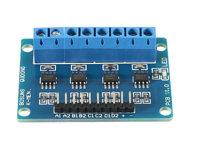
The L9110S is a dual-channel DC motor driver module designed to control up to four DC motors. It supports bidirectional control, allowing motors to operate in both forward and reverse directions. This module is widely used in robotics, automation, and DIY electronics projects due to its compact size, ease of use, and compatibility with microcontrollers like Arduino and ESP32.
Explore Projects Built with L9110S DC motor driver for 4 motors
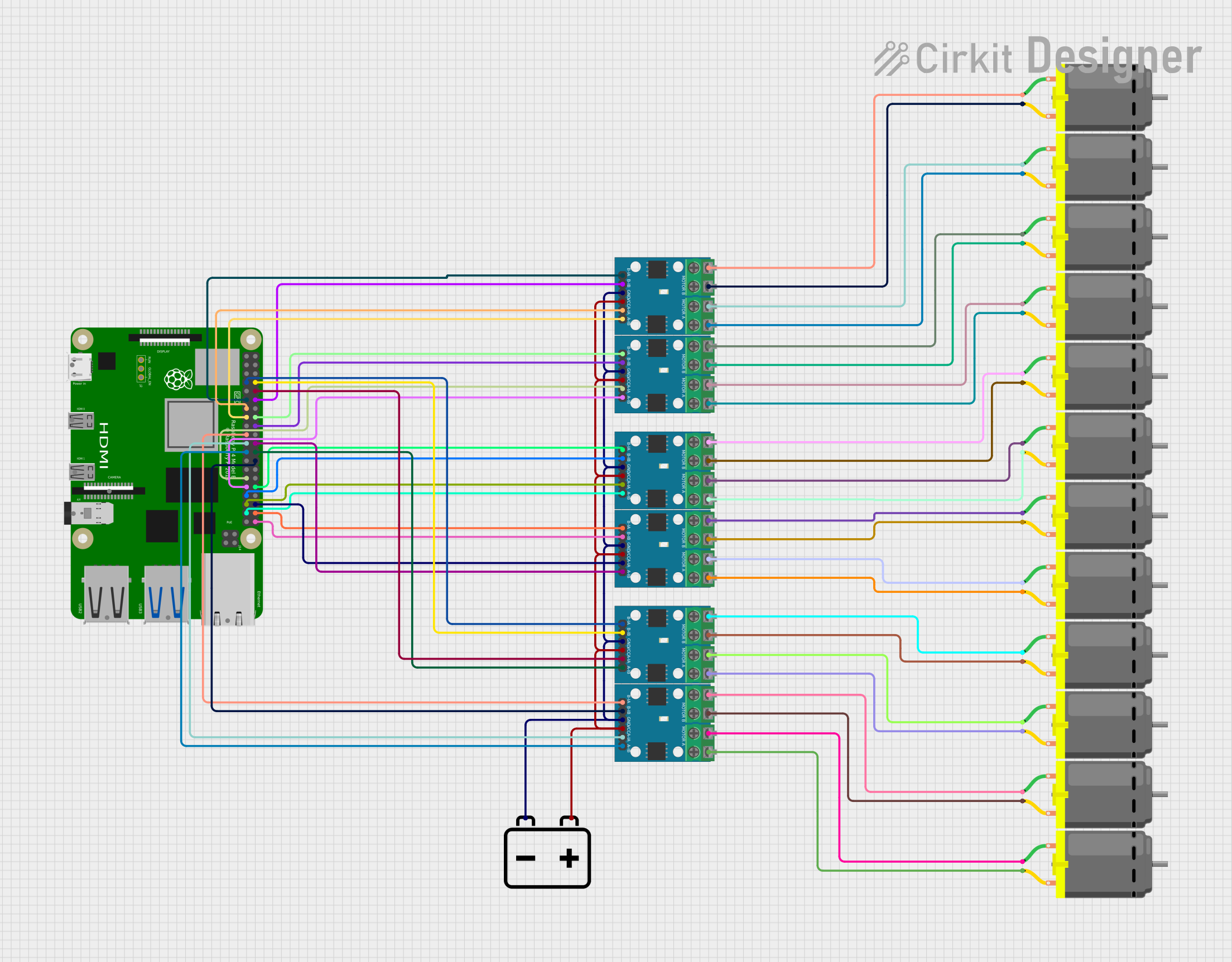
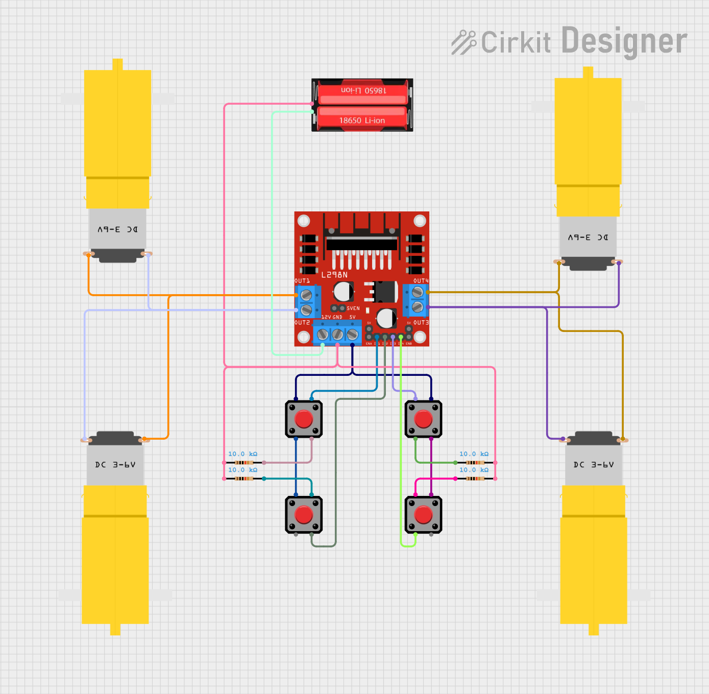
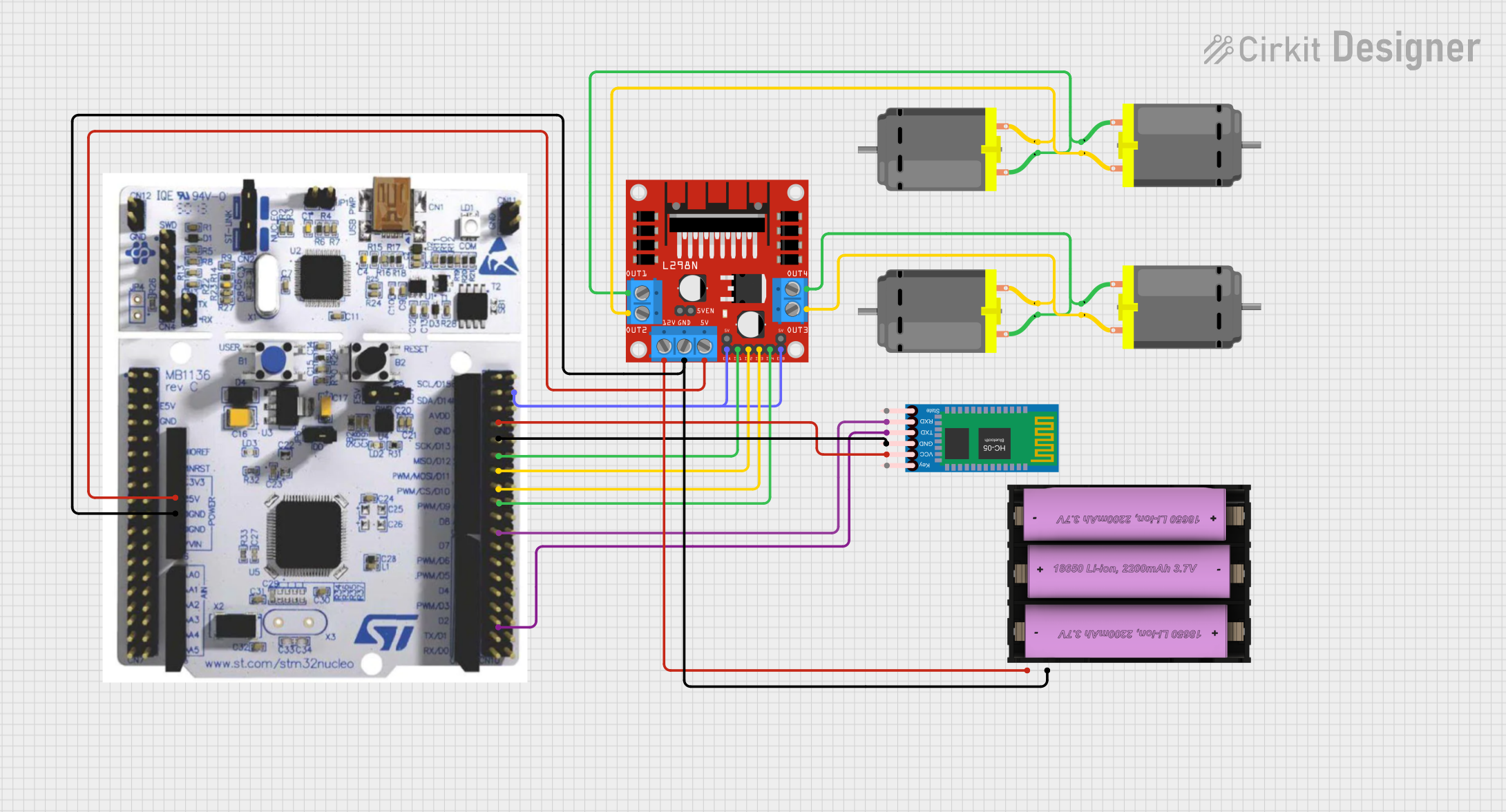
Explore Projects Built with L9110S DC motor driver for 4 motors
Common Applications and Use Cases
- Robotics: Driving wheels or tracks for mobile robots.
- Automation: Controlling conveyor belts or small mechanical systems.
- DIY Projects: Building remote-controlled cars, boats, or other motorized devices.
- Educational Projects: Learning motor control with microcontrollers.
Technical Specifications
Key Technical Details
- Operating Voltage: 2.5V to 12V DC
- Output Current: Up to 800mA per channel
- Control Logic Voltage: 3.3V to 5V (compatible with Arduino/ESP32)
- Number of Channels: 2 (each channel can control 2 motors in parallel)
- Motor Control: Forward, reverse, and stop
- Dimensions: 29mm x 23mm x 5mm
- Operating Temperature: -25°C to +85°C
Pin Configuration and Descriptions
The L9110S module has 8 pins, as described in the table below:
| Pin Name | Description |
|---|---|
| A-IA | Input signal for motor A direction control (connect to microcontroller pin). |
| A-IB | Input signal for motor A direction control (connect to microcontroller pin). |
| B-IA | Input signal for motor B direction control (connect to microcontroller pin). |
| B-IB | Input signal for motor B direction control (connect to microcontroller pin). |
| VCC | Power supply for the motors (2.5V to 12V). |
| GND | Ground connection. |
| Motor A+ | Positive terminal for Motor A. |
| Motor A- | Negative terminal for Motor A. |
| Motor B+ | Positive terminal for Motor B. |
| Motor B- | Negative terminal for Motor B. |
Usage Instructions
How to Use the Component in a Circuit
- Power Supply: Connect the VCC pin to a power source (2.5V to 12V) suitable for your motors. Connect the GND pin to the ground of your power source and microcontroller.
- Motor Connections: Connect the terminals of your DC motors to the Motor A+/A- and Motor B+/B- pins.
- Control Pins: Connect the A-IA, A-IB, B-IA, and B-IB pins to digital output pins on your microcontroller (e.g., Arduino or ESP32).
- Logic Voltage: Ensure the control logic voltage (3.3V or 5V) matches your microcontroller's output.
Important Considerations and Best Practices
- Power Supply: Use a separate power supply for the motors if they require high current, and connect the grounds of the motor power supply and microcontroller.
- Heat Dissipation: Avoid exceeding the current rating (800mA per channel) to prevent overheating.
- Decoupling Capacitors: Add capacitors near the power supply pins to reduce noise and improve stability.
- Motor Noise: Use flyback diodes across the motor terminals to suppress voltage spikes caused by motor inductance.
Example Code for Arduino UNO
Below is an example code to control two DC motors using the L9110S module with an Arduino UNO:
// Define control pins for Motor A
const int motorA_IA = 3; // Connect to A-IA pin on L9110S
const int motorA_IB = 4; // Connect to A-IB pin on L9110S

// Define control pins for Motor B
const int motorB_IA = 5; // Connect to B-IA pin on L9110S
const int motorB_IB = 6; // Connect to B-IB pin on L9110S

void setup() {
  // Set motor control pins as outputs
  pinMode(motorA_IA, OUTPUT);
  pinMode(motorA_IB, OUTPUT);
  pinMode(motorB_IA, OUTPUT);
  pinMode(motorB_IB, OUTPUT);
}

void loop() {
  // Motor A: Forward
  digitalWrite(motorA_IA, HIGH);
  digitalWrite(motorA_IB, LOW);

  // Motor B: Reverse
  digitalWrite(motorB_IA, LOW);
  digitalWrite(motorB_IB, HIGH);

  delay(2000); // Run motors for 2 seconds

  // Stop both motors
  digitalWrite(motorA_IA, LOW);
  digitalWrite(motorA_IB, LOW);
  digitalWrite(motorB_IA, LOW);
  digitalWrite(motorB_IB, LOW);

  delay(2000); // Wait for 2 seconds
}
Troubleshooting and FAQs
Common Issues and Solutions
Motors Not Running:
- Check the power supply voltage and ensure it matches the motor's requirements.
- Verify the connections between the L9110S module, motors, and microcontroller.
- Ensure the control pins are correctly configured in your code.
Overheating:
- Ensure the motor current does not exceed 800mA per channel.
- Use a heat sink or cooling fan if the module gets too hot.
Erratic Motor Behavior:
- Add decoupling capacitors near the power supply pins to reduce noise.
- Check for loose or faulty connections.
No Response from Motors:
- Verify that the microcontroller is outputting the correct logic levels (3.3V or 5V).
- Test the motors directly with a power supply to ensure they are functional.
FAQs
Q: Can I control stepper motors with the L9110S?
A: The L9110S is primarily designed for DC motors. While it can control stepper motors, a dedicated stepper motor driver is recommended for better performance.
Q: Is the L9110S compatible with 3.3V logic?
A: Yes, the L9110S is compatible with both 3.3V and 5V logic levels, making it suitable for use with Arduino, ESP32, and other microcontrollers.
Q: Can I use the L9110S to control more than four motors?
A: You can control up to four motors by connecting two motors in parallel per channel. However, ensure the total current does not exceed 800mA per channel.