Cirkit Designer Logo
Cirkit Designer
Your all-in-one circuit design IDE
Home / 
Component Documentation

How to Use Step Up Boost 3v- 5v: Examples, Pinouts, and Specs

Image of Step Up Boost 3v- 5v
Cirkit Designer LogoDesign with Step Up Boost 3v- 5v in Cirkit Designer

Introduction

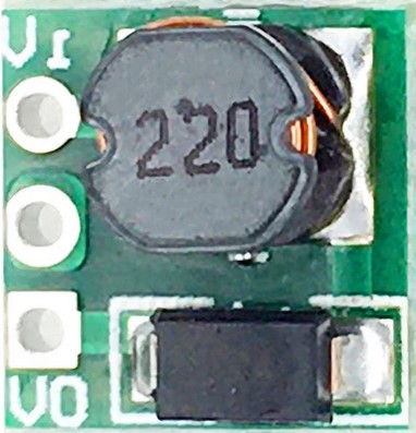
The Step Up Boost 3v-5v Power Module is a compact DC-DC converter designed by Arduino to increase a low input voltage of 3V to a stable output voltage of 5V. This module is particularly useful in battery-powered applications where the input voltage is below the required operating voltage of electronic components. Common applications include powering 5V sensors, microcontrollers like Arduino boards, and other digital devices from a lower voltage source such as AA or AAA batteries.

Explore Projects Built with Step Up Boost 3v- 5v

Use Cirkit Designer to design, explore, and prototype these projects online. Some projects support real-time simulation. Click "Open Project" to start designing instantly!
Battery-Powered 18650 Li-ion Charger with USB Output and Adjustable Voltage Regulator
Image of Breadboard: A project utilizing Step Up Boost 3v- 5v in a practical application
This circuit is a battery management and power supply system that uses three 3.7V batteries connected to a 3S 10A Li-ion 18650 Charger Protection Board Module for balanced charging and protection. The system includes a TP4056 Battery Charging Protection Module for additional charging safety, a Step Up Boost Power Converter to regulate and boost the voltage, and a USB regulator to provide a stable 5V output, controlled by a push switch.
Cirkit Designer LogoOpen Project in Cirkit Designer
Battery-Powered High Voltage Generator with Copper Coil
Image of Ionic Thruster Mark_1: A project utilizing Step Up Boost 3v- 5v in a practical application
This circuit consists of a Li-ion battery connected to a step-up power module through a rocker switch, which boosts the voltage to power a ring of copper gauge with an aluminum frame. The rocker switch allows the user to control the power flow from the battery to the step-up module, which then supplies the boosted voltage to the copper ring.
Cirkit Designer LogoOpen Project in Cirkit Designer
Battery-Powered Adjustable Voltage Regulator with Power Jack
Image of batteries : A project utilizing Step Up Boost 3v- 5v in a practical application
This circuit takes a 7V input from a battery and uses a Step Up Boost Power Converter to increase the voltage to a higher, adjustable level. The boosted voltage is then supplied to a power jack for external use.
Cirkit Designer LogoOpen Project in Cirkit Designer
Battery-Powered Lora G2 Node Station with 18650 Li-ion Batteries and Boost Converter
Image of Custom-Lora-G2-Node: A project utilizing Step Up Boost 3v- 5v in a practical application
This circuit is a portable power supply system that uses multiple 18650 Li-ion batteries to provide a stable 5V output through a boost converter. It includes a fast charging module with a USB-C input for recharging the batteries and a battery indicator for monitoring the battery status. The system powers a Lora G2 Node Station, making it suitable for wireless communication applications.
Cirkit Designer LogoOpen Project in Cirkit Designer

Explore Projects Built with Step Up Boost 3v- 5v

Use Cirkit Designer to design, explore, and prototype these projects online. Some projects support real-time simulation. Click "Open Project" to start designing instantly!
Image of Breadboard: A project utilizing Step Up Boost 3v- 5v in a practical application
Battery-Powered 18650 Li-ion Charger with USB Output and Adjustable Voltage Regulator
This circuit is a battery management and power supply system that uses three 3.7V batteries connected to a 3S 10A Li-ion 18650 Charger Protection Board Module for balanced charging and protection. The system includes a TP4056 Battery Charging Protection Module for additional charging safety, a Step Up Boost Power Converter to regulate and boost the voltage, and a USB regulator to provide a stable 5V output, controlled by a push switch.
Cirkit Designer LogoOpen Project in Cirkit Designer
Image of Ionic Thruster Mark_1: A project utilizing Step Up Boost 3v- 5v in a practical application
Battery-Powered High Voltage Generator with Copper Coil
This circuit consists of a Li-ion battery connected to a step-up power module through a rocker switch, which boosts the voltage to power a ring of copper gauge with an aluminum frame. The rocker switch allows the user to control the power flow from the battery to the step-up module, which then supplies the boosted voltage to the copper ring.
Cirkit Designer LogoOpen Project in Cirkit Designer
Image of batteries : A project utilizing Step Up Boost 3v- 5v in a practical application
Battery-Powered Adjustable Voltage Regulator with Power Jack
This circuit takes a 7V input from a battery and uses a Step Up Boost Power Converter to increase the voltage to a higher, adjustable level. The boosted voltage is then supplied to a power jack for external use.
Cirkit Designer LogoOpen Project in Cirkit Designer
Image of Custom-Lora-G2-Node: A project utilizing Step Up Boost 3v- 5v in a practical application
Battery-Powered Lora G2 Node Station with 18650 Li-ion Batteries and Boost Converter
This circuit is a portable power supply system that uses multiple 18650 Li-ion batteries to provide a stable 5V output through a boost converter. It includes a fast charging module with a USB-C input for recharging the batteries and a battery indicator for monitoring the battery status. The system powers a Lora G2 Node Station, making it suitable for wireless communication applications.
Cirkit Designer LogoOpen Project in Cirkit Designer

Technical Specifications

Key Technical Details

  • Input Voltage: 3V (minimum)
  • Output Voltage: 5V (fixed)
  • Maximum Output Current: Varies with input voltage and load (refer to manufacturer's datasheet)
  • Efficiency: Typically 85-90% (depends on input voltage and load)
  • Operating Temperature: -40°C to +85°C (industrial grade)

Pin Configuration and Descriptions

Pin Number Name Description
1 VIN Input voltage (3V)
2 GND Ground connection
3 VOUT Output voltage (5V)
4 GND Ground connection

Usage Instructions

How to Use the Component in a Circuit

  1. Connecting Input Power:

    • Connect the positive terminal of the 3V power source to the VIN pin.
    • Connect the negative terminal of the power source to one of the GND pins.
  2. Accessing the Output Power:

    • Connect the positive terminal of the device that requires 5V to the VOUT pin.
    • Connect the negative terminal of the device to the other GND pin.
  3. Powering an Arduino:

    • If you're using the module to power an Arduino, connect VOUT to the 5V pin on the Arduino board.

Important Considerations and Best Practices

  • Input Voltage: Do not exceed the recommended input voltage as it may damage the module.
  • Output Load: Ensure that the connected load does not draw more current than the module can provide.
  • Heat Dissipation: If the module is running hot, consider adding a heat sink or reducing the load.
  • Bypass Capacitors: It is recommended to use bypass capacitors close to the input and output pins for stability, especially if the power lines are long or the load is highly variable.

Troubleshooting and FAQs

Common Issues

  • Output Voltage is Low or Unstable:

    • Check if the input voltage is at least 3V.
    • Ensure that the load does not exceed the module's maximum current rating.
    • Verify that all connections are secure and there are no loose wires.
  • Module is Overheating:

    • Reduce the load on the module.
    • Improve air circulation around the module or add a heat sink.

FAQs

  • Q: Can I adjust the output voltage?

    • A: No, this module provides a fixed 5V output.
  • Q: What is the maximum input voltage I can apply?

    • A: The module is designed for a 3V input. Applying more than this may damage the module.
  • Q: Can I use this module to charge 5V devices?

    • A: This module is not designed as a charger; it is a power supply module. Ensure that the device's charging requirements are compatible with the module's output.

Example Arduino Code

// This example demonstrates how to use the Step Up Boost 3v-5v Power Module
// to power an Arduino UNO which operates at 5V.

void setup() {
  // Initialize the digital pin as an output.
  pinMode(LED_BUILTIN, OUTPUT); // Most Arduino boards have an on-board LED
}

void loop() {
  digitalWrite(LED_BUILTIN, HIGH); // Turn the LED on
  delay(1000);                     // Wait for a second
  digitalWrite(LED_BUILTIN, LOW);  // Turn the LED off
  delay(1000);                     // Wait for a second
}

// Note: The above code assumes that the Arduino is powered using the Step Up Boost
// module connected to the 5V and GND pins of the Arduino. The built-in LED will
// blink as a simple test to confirm that the power supply is working correctly.

Remember to adhere to the 80 character line length limit for code comments, wrapping text as necessary. This example code is a simple blink sketch that can be used to verify the functionality of the Step Up Boost 3v-5v Power Module when powering an Arduino UNO.