How to Use Linear Actuator: Examples, Pinouts, and Specs
Introduction
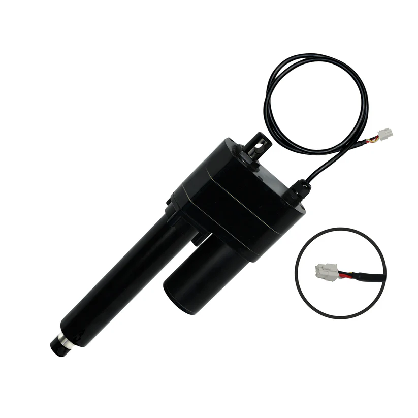
The PA-17-POT Linear Actuator is a robust and powerful actuator designed by Progressive Automations. It is specifically engineered to provide precise linear motion control in various applications, including but not limited to automation systems, industrial machinery, and vehicular automation. The built-in potentiometer allows for position feedback, which is essential for applications requiring precise control of the actuator extension.
Explore Projects Built with Linear Actuator
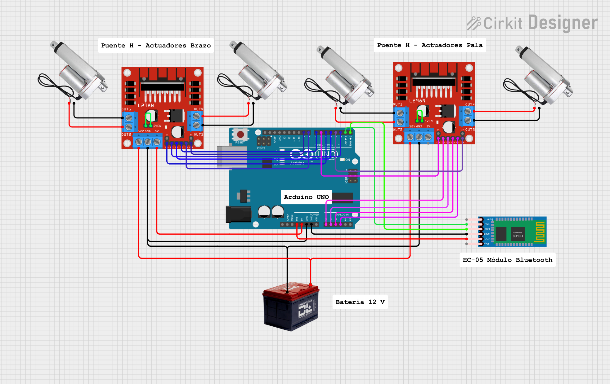
Explore Projects Built with Linear Actuator
Common Applications and Use Cases
- Industrial machine control
- Automotive automation
- Robotics and automated assembly lines
- Adjustable desks and ergonomic furniture
- Marine and outdoor applications
Technical Specifications
Key Technical Details
- Voltage: 12V DC
- Stroke Sizes: 1-40 inches
- Force: Up to 850 lbs
- Speed: 0.33 inches/sec at no load
- Duty Cycle: 20%
- IP Rating: IP66 (Dust and Water Resistant)
Pin Configuration and Descriptions
| Pin Number | Description | Notes |
|---|---|---|
| 1 | Power (+12V DC) | Red wire |
| 2 | Ground (0V) | Black wire |
| 3 | Potentiometer Wiper Output | White wire (Position Feedback) |
| 4 | Potentiometer +5V Reference | Typically not used externally |
| 5 | Potentiometer Ground | Typically not used externally |
Usage Instructions
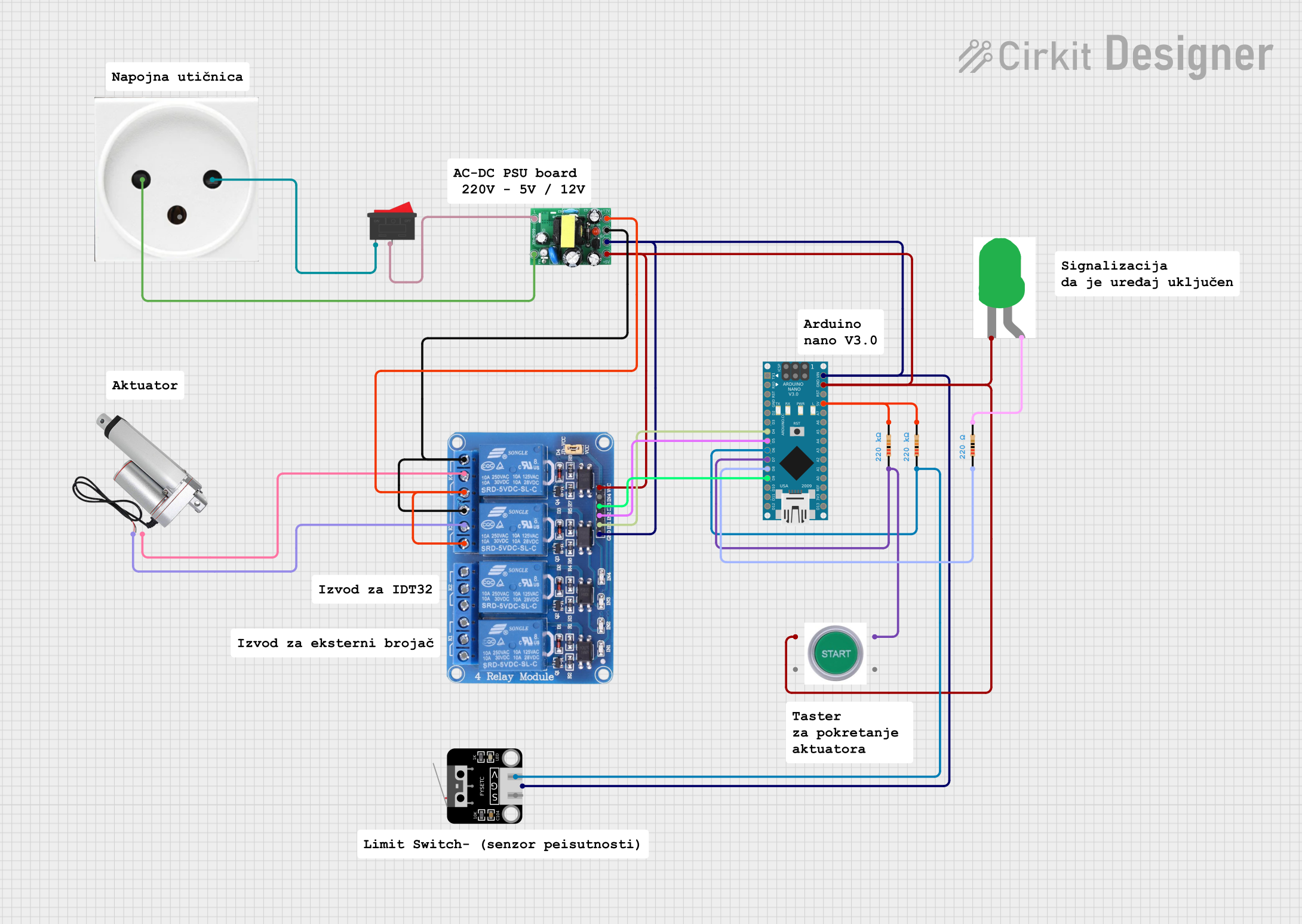
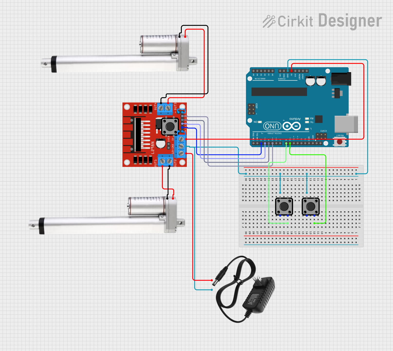
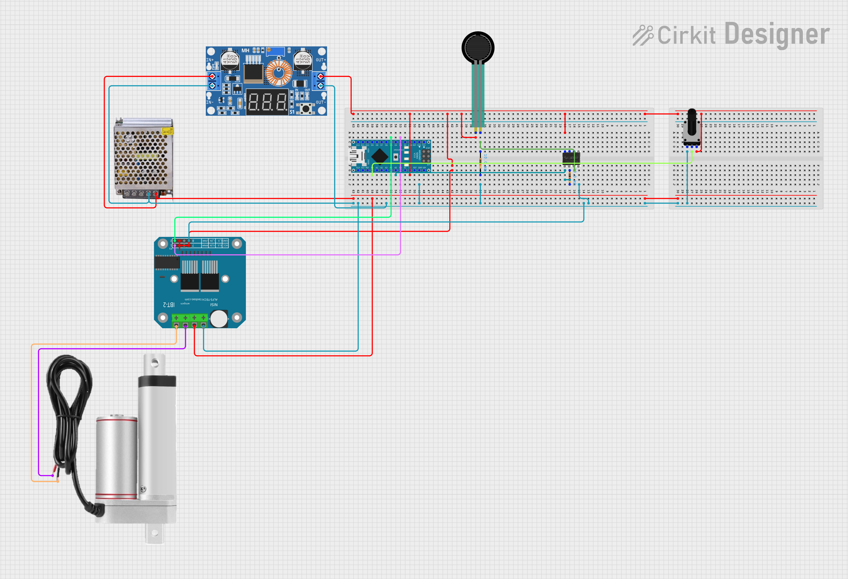
How to Use the Component in a Circuit
- Power Connection: Connect the red wire to the +12V DC power supply and the black wire to the ground.
- Control: Use a DPDT (Double Pole Double Throw) switch or a relay module to reverse the polarity for extending and retracting the actuator.
- Position Feedback: Connect the white wire to an analog input of a microcontroller to read the position of the actuator.
Important Considerations and Best Practices
- Ensure the power supply can handle the current requirements of the actuator.
- Do not exceed the rated force or speed to prevent damage.
- Use diodes for back EMF protection when switching the actuator direction.
- Avoid side loads which can cause premature wear or failure.
- Regularly inspect for any signs of wear or damage.
Example Arduino Code
// Define the connection pins
const int potPin = A0; // Potentiometer wiper (position feedback) connected to analog pin A0
const int actuatorPin1 = 2; // Actuator pin 1 connected to digital pin 2
const int actuatorPin2 = 3; // Actuator pin 2 connected to digital pin 3

void setup() {
  pinMode(actuatorPin1, OUTPUT);
  pinMode(actuatorPin2, OUTPUT);
  Serial.begin(9600);
}

void loop() {
  int potValue = analogRead(potPin); // Read the potentiometer value
  Serial.println(potValue); // Print the potentiometer value to the serial monitor

  // Extend the actuator
  digitalWrite(actuatorPin1, HIGH);
  digitalWrite(actuatorPin2, LOW);
  delay(1000); // Wait for 1 second

  // Retract the actuator
  digitalWrite(actuatorPin1, LOW);
  digitalWrite(actuatorPin2, HIGH);
  delay(1000); // Wait for 1 second

  // Stop the actuator
  digitalWrite(actuatorPin1, LOW);
  digitalWrite(actuatorPin2, LOW);
  delay(1000); // Wait for 1 second
}
Troubleshooting and FAQs
Common Issues
- Actuator not moving: Check power supply and wiring connections.
- Actuator moving erratically: Verify that the potentiometer wiring is secure and not damaged.
- Noisy operation or vibration: Inspect for mechanical obstructions or misalignment.
Solutions and Tips for Troubleshooting
- Ensure all connections are secure and free from corrosion.
- Use a multimeter to check for continuity and proper voltage levels.
- If the actuator is not responding, try isolating the problem by testing the actuator with a separate power supply.
FAQs
Q: Can the PA-17-POT be used outdoors? A: Yes, with an IP66 rating, it is dust and water-resistant, suitable for outdoor use.
Q: What is the purpose of the built-in potentiometer? A: The potentiometer provides position feedback, which can be used for precise control of the actuator's extension and retraction.
Q: How can I control the speed of the actuator? A: The speed can be controlled by using a PWM signal to modulate the power supplied to the actuator.
Q: What should I do if the actuator is not extending or retracting to its full length? A: Check if the duty cycle is being exceeded or if there is an obstruction. Also, verify that the potentiometer is functioning correctly and providing accurate feedback.
For further assistance, contact Progressive Automations' technical support.