How to Use Screw Terminal 10P 0.2" Pitch: Examples, Pinouts, and Specs
Introduction
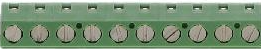
The Screw Terminal 10P 0.2" Pitch is a 10-position screw terminal block designed for secure and reliable wire connections in electronic circuits. With a pitch of 0.2 inches (5.08 mm), this component is ideal for connecting multiple wires to a PCB or other electronic systems. It is widely used in prototyping, industrial control systems, and DIY electronics projects due to its ease of use and robust connection mechanism.
Explore Projects Built with Screw Terminal 10P 0.2" Pitch


Explore Projects Built with Screw Terminal 10P 0.2" Pitch
Common Applications and Use Cases
- Prototyping and Development: Quickly connect and disconnect wires during circuit testing.
- Industrial Control Systems: Securely connect sensors, actuators, and other devices.
- Power Distribution: Distribute power to multiple components in a circuit.
- DIY Electronics: Ideal for hobbyists building custom electronic projects.
Technical Specifications
Below are the key technical details of the Screw Terminal 10P 0.2" Pitch:
| Parameter | Value |
|---|---|
| Manufacturer | N/A |
| Manufacturer Part ID | Screw Terminal 10P 0.2" Pitch |
| Number of Positions | 10 |
| Pitch (Pin Spacing) | 0.2 inches (5.08 mm) |
| Wire Gauge Support | 26 AWG to 14 AWG |
| Maximum Voltage Rating | 300V AC/DC |
| Maximum Current Rating | 15A |
| Material (Housing) | Polyamide (PA66), flame-retardant |
| Contact Material | Tin-plated copper alloy |
| Operating Temperature | -40°C to +105°C |
| Mounting Type | Through-hole or PCB mount |
Pin Configuration and Descriptions
The Screw Terminal 10P 0.2" Pitch has 10 positions, each corresponding to a screw terminal for wire connections. Below is the pin configuration:
| Pin Number | Description |
|---|---|
| 1 to 10 | Wire connection points (1 per pin) |
| Mounting Pins | Mechanical support for PCB mounting |
Usage Instructions
How to Use the Component in a Circuit
Prepare the Wires:
- Strip the insulation from the wire ends (approximately 5-7 mm).
- Ensure the wire gauge is within the supported range (26 AWG to 14 AWG).
Insert the Wires:
- Loosen the screw on the desired terminal using a small flathead screwdriver.
- Insert the stripped wire end into the terminal opening.
Secure the Connection:
- Tighten the screw to clamp the wire securely in place.
- Avoid overtightening, as this may damage the wire or terminal.
Mount the Terminal Block:
- If using a PCB, solder the mounting pins to the board.
- Ensure proper alignment with the circuit design.
Connect to the Circuit:
- Use the terminal block to connect wires to other components, such as sensors, power supplies, or microcontrollers.
Important Considerations and Best Practices
- Wire Preparation: Ensure wires are properly stripped and free of frayed strands to avoid poor connections.
- Tightening Screws: Do not overtighten screws, as this can strip the threads or damage the terminal.
- Current and Voltage Ratings: Do not exceed the maximum current (15A) or voltage (300V) ratings to prevent overheating or failure.
- PCB Design: When mounting on a PCB, ensure the hole spacing matches the 0.2-inch pitch of the terminal block.
- Environmental Conditions: Use the terminal block within the specified operating temperature range (-40°C to +105°C).
Example: Connecting to an Arduino UNO
The Screw Terminal 10P 0.2" Pitch can be used to connect external components, such as sensors or motors, to an Arduino UNO. Below is an example of wiring a sensor to an Arduino using the terminal block:
- Connect the sensor's power (VCC) and ground (GND) wires to the terminal block.
- Use jumper wires to connect the corresponding terminal block pins to the Arduino's 5V and GND pins.
- Connect the sensor's signal wire to another terminal block pin, and then to an Arduino input pin (e.g., A0).
Here is a sample Arduino code snippet for reading an analog sensor value:
// Define the analog pin connected to the sensor
const int sensorPin = A0;

void setup() {
  // Initialize serial communication for debugging
  Serial.begin(9600);
}

void loop() {
  // Read the sensor value from the analog pin
  int sensorValue = analogRead(sensorPin);

  // Print the sensor value to the Serial Monitor
  Serial.print("Sensor Value: ");
  Serial.println(sensorValue);

  // Add a short delay for stability
  delay(500);
}
Troubleshooting and FAQs
Common Issues Users Might Face
Loose Connections:
- Problem: Wires are not securely clamped, leading to intermittent connections.
- Solution: Ensure screws are tightened properly and wires are fully inserted.
Overheating:
- Problem: Terminal block overheats during operation.
- Solution: Check that the current and voltage do not exceed the specified ratings.
Wire Slippage:
- Problem: Wires slip out of the terminal block.
- Solution: Verify that the wire gauge is within the supported range and that screws are tightened.
PCB Mounting Issues:
- Problem: Terminal block does not align with PCB holes.
- Solution: Ensure the PCB design matches the 0.2-inch pitch of the terminal block.
FAQs
Can this terminal block be used for high-power applications?
- Yes, it supports up to 15A and 300V, making it suitable for many high-power applications.
What tools are required to use this terminal block?
- A small flathead screwdriver is needed to tighten or loosen the screws.
Can I use stranded wires with this terminal block?
- Yes, stranded wires are supported. However, ensure the strands are twisted or use ferrules for a more secure connection.
Is this terminal block reusable?
- Yes, it can be reused multiple times as long as it is not physically damaged.
By following the guidelines and best practices outlined in this documentation, users can effectively integrate the Screw Terminal 10P 0.2" Pitch into their electronic projects.