Cirkit Designer
Your all-in-one circuit design IDE
Home /
Component Documentation
How to Use ESP32 R8 Camera: Examples, Pinouts, and Specs
Introduction
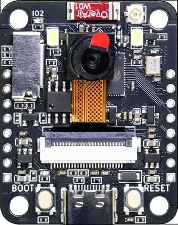
The ESP32 R8 Camera is a compact, low-cost camera module that integrates an ESP32 microcontroller, providing built-in Wi-Fi and Bluetooth connectivity. This module is designed for IoT applications, enabling image capture, video streaming, and remote monitoring. With its onboard camera sensor, the ESP32 R8 Camera supports various image resolutions, making it suitable for projects such as home automation, security systems, and AI-based image recognition.
Explore Projects Built with ESP32 R8 Camera
ESP32-Controlled OLED Display and TTL Serial Camera Interface
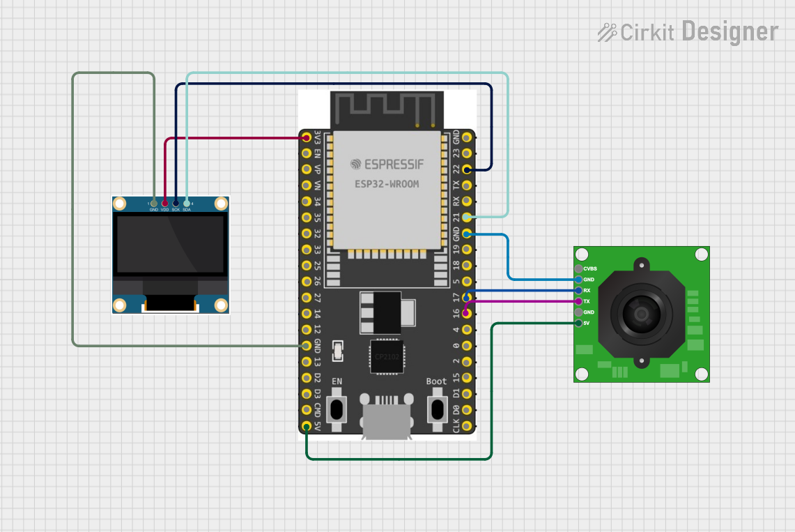
This circuit features an ESP32 microcontroller connected to a TTL Serial JPEG Camera and a 0.96" OLED display. The ESP32 is configured to communicate with the camera over serial connections (TX/RX) to capture and possibly process images. Additionally, the ESP32 drives the OLED display via I2C (SCK/SDA) to show information or images to the user.
ESP32 CAM Wi-Fi Controlled Camera with FTDI Programmer

This circuit consists of an ESP32 CAM module connected to an FTDI Programmer for power and serial communication. The ESP32 CAM is programmed to capture images and stream them over WiFi, acting as a web server to provide live video feed.
ESP32 CAM Wi-Fi Controlled Camera with FTDI Programmer

This circuit consists of an ESP32 CAM module connected to an FTDI Programmer for power and serial communication. The ESP32 CAM is programmed to capture images and stream them over WiFi, acting as a web server to provide a live video feed.
ESP32 CAM PIR Sensor Security Camera with Battery Management
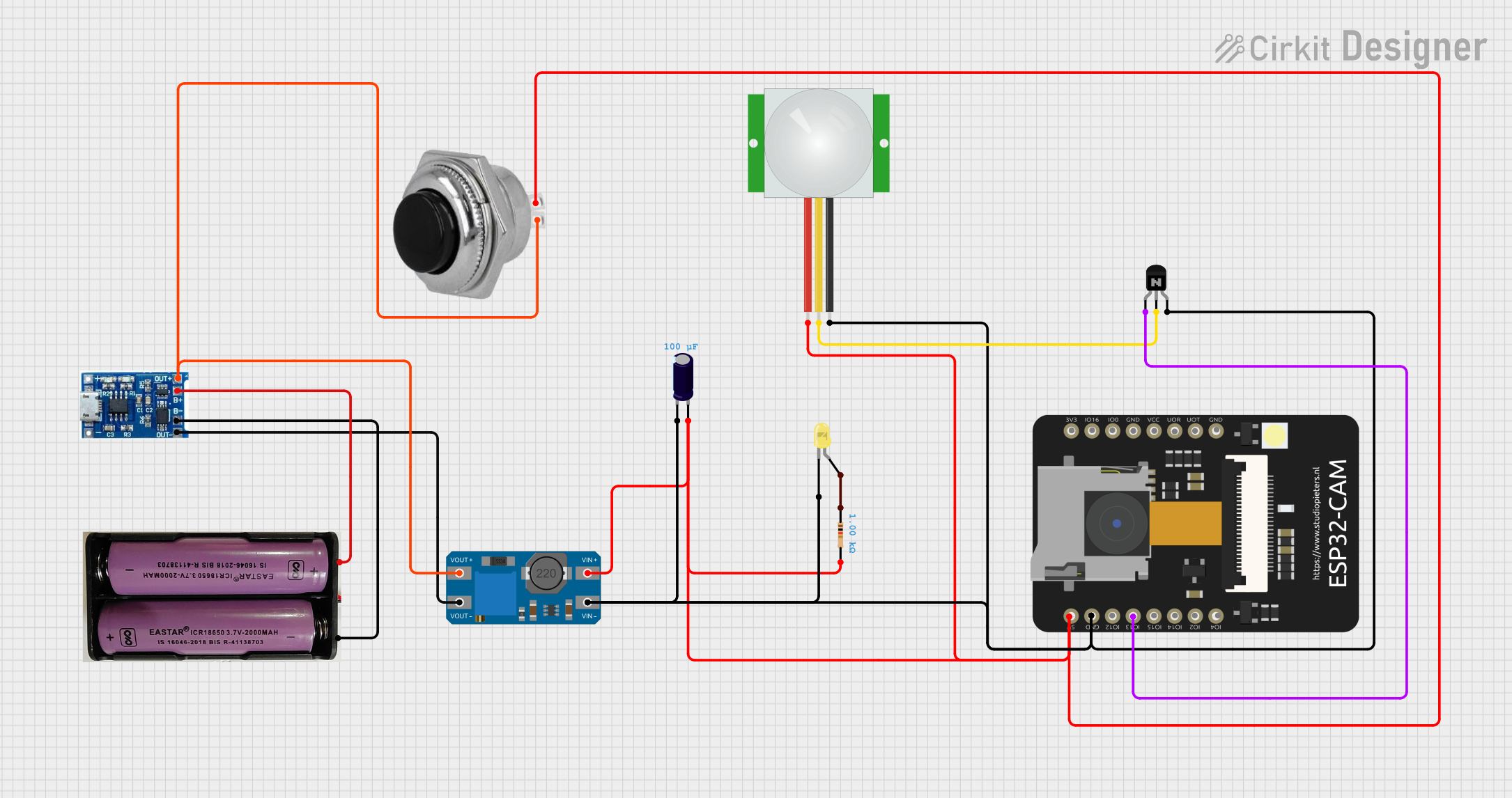
This is a motion-activated camera system powered by a 7.4V battery with a charging module. It uses a PIR sensor to detect motion and an ESP32 CAM microcontroller to process the signal and activate a yellow LED through an NPN transistor. A voltage booster and capacitor are included for power management, and a momentary switch allows for manual power control.
Explore Projects Built with ESP32 R8 Camera
ESP32-Controlled OLED Display and TTL Serial Camera Interface
This circuit features an ESP32 microcontroller connected to a TTL Serial JPEG Camera and a 0.96" OLED display. The ESP32 is configured to communicate with the camera over serial connections (TX/RX) to capture and possibly process images. Additionally, the ESP32 drives the OLED display via I2C (SCK/SDA) to show information or images to the user.
ESP32 CAM Wi-Fi Controlled Camera with FTDI Programmer
This circuit consists of an ESP32 CAM module connected to an FTDI Programmer for power and serial communication. The ESP32 CAM is programmed to capture images and stream them over WiFi, acting as a web server to provide live video feed.
ESP32 CAM Wi-Fi Controlled Camera with FTDI Programmer
This circuit consists of an ESP32 CAM module connected to an FTDI Programmer for power and serial communication. The ESP32 CAM is programmed to capture images and stream them over WiFi, acting as a web server to provide a live video feed.
ESP32 CAM PIR Sensor Security Camera with Battery Management
This is a motion-activated camera system powered by a 7.4V battery with a charging module. It uses a PIR sensor to detect motion and an ESP32 CAM microcontroller to process the signal and activate a yellow LED through an NPN transistor. A voltage booster and capacitor are included for power management, and a momentary switch allows for manual power control.
Common Applications:
- Home security and surveillance systems
- IoT-based image capture and streaming
- AI and machine learning projects (e.g., facial recognition)
- Remote monitoring and control
- DIY robotics and drones
Technical Specifications
Key Technical Details:
| Parameter | Specification |
|---|---|
| Microcontroller | ESP32 |
| Connectivity | Wi-Fi 802.11 b/g/n, Bluetooth 4.2 |
| Camera Sensor | OV2640 |
| Image Resolutions | Up to 1600x1200 (UXGA) |
| Flash Memory | 4 MB SPI Flash |
| RAM | 520 KB SRAM + 4 MB PSRAM |
| Operating Voltage | 3.3V |
| Power Consumption | ~160 mA (active), ~10 µA (deep sleep) |
| Interfaces | GPIO, I2C, SPI, UART, PWM |
| Dimensions | 40mm x 27mm |
Pin Configuration and Descriptions:
| Pin Name | Pin Number | Description |
|---|---|---|
| 3V3 | 1 | Power input (3.3V) |
| GND | 2 | Ground |
| GPIO0 | 3 | Boot mode selection (connect to GND for flashing) |
| GPIO2 | 4 | General-purpose I/O, often used for LED |
| GPIO16 | 5 | General-purpose I/O |
| GPIO17 | 6 | General-purpose I/O |
| SDA | 7 | I2C data line |
| SCL | 8 | I2C clock line |
| RX | 9 | UART receive |
| TX | 10 | UART transmit |
| RESET | 11 | Reset pin |
Usage Instructions
How to Use the ESP32 R8 Camera in a Circuit:
- Power the Module: Connect the 3V3 pin to a 3.3V power source and GND to ground.
- Connect to a Microcontroller (if needed): Use the UART pins (RX and TX) or I2C pins (SDA and SCL) to interface with an external microcontroller.
- Flashing Firmware:
- Connect GPIO0 to GND to enable boot mode.
- Use a USB-to-serial adapter to connect the module to your computer.
- Flash the firmware using tools like the ESP-IDF or Arduino IDE.
- Camera Initialization:
- Use the ESP32 Camera library in the Arduino IDE or ESP-IDF to initialize the camera.
- Configure the resolution and frame rate as needed.
Important Considerations:
- Power Supply: Ensure a stable 3.3V power source to avoid damage to the module.
- Heat Management: The ESP32 may heat up during operation; ensure proper ventilation.
- Antenna Placement: Avoid placing the module near metal objects to maintain good Wi-Fi signal strength.
- GPIO Usage: Some GPIO pins are reserved for internal functions; consult the datasheet before use.
Example Code for Arduino IDE:
#include "esp_camera.h"

// Define the camera pin configuration
#define PWDN_GPIO_NUM    -1 // Power down pin (not used)
#define RESET_GPIO_NUM   -1 // Reset pin (not used)
#define XCLK_GPIO_NUM     0 // XCLK pin
#define SIOD_GPIO_NUM    26 // I2C data pin
#define SIOC_GPIO_NUM    27 // I2C clock pin
#define Y9_GPIO_NUM      35 // Y9 pin
#define Y8_GPIO_NUM      34 // Y8 pin
#define Y7_GPIO_NUM      39 // Y7 pin
#define Y6_GPIO_NUM      36 // Y6 pin
#define Y5_GPIO_NUM      21 // Y5 pin
#define Y4_GPIO_NUM      19 // Y4 pin
#define Y3_GPIO_NUM      18 // Y3 pin
#define Y2_GPIO_NUM       5 // Y2 pin
#define VSYNC_GPIO_NUM   25 // VSYNC pin
#define HREF_GPIO_NUM    23 // HREF pin
#define PCLK_GPIO_NUM    22 // PCLK pin

void setup() {
  Serial.begin(115200);

  // Camera configuration
  camera_config_t config;
  config.ledc_channel = LEDC_CHANNEL_0;
  config.ledc_timer = LEDC_TIMER_0;
  config.pin_d0 = Y2_GPIO_NUM;
  config.pin_d1 = Y3_GPIO_NUM;
  config.pin_d2 = Y4_GPIO_NUM;
  config.pin_d3 = Y5_GPIO_NUM;
  config.pin_d4 = Y6_GPIO_NUM;
  config.pin_d5 = Y7_GPIO_NUM;
  config.pin_d6 = Y8_GPIO_NUM;
  config.pin_d7 = Y9_GPIO_NUM;
  config.pin_xclk = XCLK_GPIO_NUM;
  config.pin_pclk = PCLK_GPIO_NUM;
  config.pin_vsync = VSYNC_GPIO_NUM;
  config.pin_href = HREF_GPIO_NUM;
  config.pin_sscb_sda = SIOD_GPIO_NUM;
  config.pin_sscb_scl = SIOC_GPIO_NUM;
  config.pin_pwdn = PWDN_GPIO_NUM;
  config.pin_reset = RESET_GPIO_NUM;
  config.xclk_freq_hz = 20000000; // 20 MHz
  config.pixel_format = PIXFORMAT_JPEG; // Output format

  // Initialize the camera
  if (esp_camera_init(&config) != ESP_OK) {
    Serial.println("Camera initialization failed!");
    return;
  }
  Serial.println("Camera initialized successfully!");
}

void loop() {
  // Capture a frame
  camera_fb_t *fb = esp_camera_fb_get();
  if (!fb) {
    Serial.println("Failed to capture image!");
    return;
  }

  // Print the size of the captured image
  Serial.printf("Captured image size: %d bytes\n", fb->len);

  // Return the frame buffer to the driver for reuse
  esp_camera_fb_return(fb);

  delay(1000); // Wait 1 second before capturing the next frame
}
Troubleshooting and FAQs
Common Issues:
Camera Initialization Fails:
- Cause: Incorrect pin configuration or insufficient power supply.
- Solution: Double-check the pin assignments and ensure a stable 3.3V power source.
Wi-Fi Connection Issues:
- Cause: Poor antenna placement or incorrect Wi-Fi credentials.
- Solution: Ensure the module is placed away from metal objects and verify the Wi-Fi credentials.
Image Quality is Poor:
- Cause: Incorrect resolution settings or poor lighting conditions.
- Solution: Adjust the resolution and ensure adequate lighting.
Module Overheats:
- Cause: Prolonged operation or insufficient ventilation.
- Solution: Add a heat sink or improve airflow around the module.
FAQs:
Q: Can the ESP32 R8 Camera stream video?
- A: Yes, it supports video streaming over Wi-Fi using protocols like HTTP or RTSP.
Q: What is the maximum image resolution?
- A: The module supports resolutions up to 1600x1200 (UXGA).
Q: Can I use this module with an Arduino UNO?
- A: No, the ESP32 R8 Camera requires more processing power and memory than the Arduino UNO can provide. Use it as a standalone module or with other ESP32-based boards.
Q: How do I update the firmware?
- A: Use the ESP-IDF or Arduino IDE to flash new firmware via the UART interface.