How to Use TFT 1.77" SPI ST7735: Examples, Pinouts, and Specs
Introduction
The TFT 1.77" SPI ST7735 is a compact, full-color thin-film transistor (TFT) display module with a resolution of 128x160 pixels. It utilizes the ST7735 driver IC and communicates via the Serial Peripheral Interface (SPI), making it ideal for embedded systems and microcontroller-based projects. This display is capable of rendering vibrant graphics and text, making it suitable for applications such as user interfaces, data visualization, and gaming.
Explore Projects Built with TFT 1.77" SPI ST7735


Explore Projects Built with TFT 1.77" SPI ST7735
Common Applications and Use Cases
- Embedded systems requiring graphical displays
- IoT devices with visual feedback
- Portable gaming consoles
- Wearable devices
- Industrial control panels
- Educational projects with microcontrollers like Arduino or Raspberry Pi
Technical Specifications
Below are the key technical details and pin configuration for the TFT 1.77" SPI ST7735:
Key Technical Details
| Parameter | Specification |
|---|---|
| Display Type | TFT LCD |
| Driver IC | ST7735 |
| Screen Size | 1.77 inches |
| Resolution | 128x160 pixels |
| Communication Interface | SPI (Serial Peripheral Interface) |
| Operating Voltage | 3.3V (logic and backlight) |
| Current Consumption | ~50mA (typical) |
| Color Depth | 18-bit (262,144 colors) |
| Backlight | LED |
| Dimensions | 34.5mm x 46.5mm x 4.5mm |
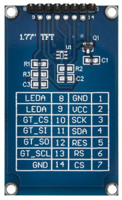
Pin Configuration and Descriptions
| Pin Name | Pin Number | Description |
|---|---|---|
| GND | 1 | Ground connection |
| VCC | 2 | Power supply (3.3V recommended) |
| SCL | 3 | SPI clock line (SCK) |
| SDA | 4 | SPI data line (MOSI) |
| RES | 5 | Reset pin (active low) |
| DC | 6 | Data/Command control pin (High = Data, Low = Command) |
| CS | 7 | Chip select (active low) |
| BLK | 8 | Backlight control (connect to 3.3V for always-on or PWM for brightness) |
Usage Instructions
How to Use the Component in a Circuit
- Power Supply: Connect the
VCCpin to a 3.3V power source and theGNDpin to ground. - SPI Connections:
- Connect the
SCLpin to the SPI clock pin of your microcontroller. - Connect the
SDApin to the SPI MOSI pin of your microcontroller.
- Connect the
- Control Pins:
- Connect the
RESpin to a GPIO pin for resetting the display. - Connect the
DCpin to a GPIO pin to toggle between data and command modes. - Connect the
CSpin to a GPIO pin to enable/disable the display.
- Connect the
- Backlight: Connect the
BLKpin to 3.3V for constant backlight or to a PWM pin for brightness control.
Important Considerations and Best Practices
- Voltage Levels: Ensure all logic signals are 3.3V. If using a 5V microcontroller (e.g., Arduino UNO), use level shifters to avoid damaging the display.
- SPI Speed: Use an appropriate SPI clock speed (typically up to 15 MHz) to ensure reliable communication.
- Initialization: The ST7735 driver requires specific initialization commands. Use a compatible library (e.g., Adafruit GFX and Adafruit ST7735 libraries) to simplify this process.
- Backlight Control: Use a PWM signal on the
BLKpin to adjust brightness dynamically.
Example Code for Arduino UNO
Below is an example of how to use the TFT 1.77" SPI ST7735 with an Arduino UNO:
#include <Adafruit_GFX.h>      // Graphics library for displays
#include <Adafruit_ST7735.h>   // Library for ST7735 driver

// Define pin connections
#define TFT_CS     10  // Chip select pin
#define TFT_RST    9   // Reset pin
#define TFT_DC     8   // Data/Command pin

// Create an instance of the display
Adafruit_ST7735 tft = Adafruit_ST7735(TFT_CS, TFT_DC, TFT_RST);

void setup() {
  // Initialize the display
  tft.initR(INITR_BLACKTAB);  // Initialize with ST7735 Black Tab configuration
  tft.setRotation(1);        // Set display orientation (1 = landscape)

  // Clear the screen with a black background
  tft.fillScreen(ST77XX_BLACK);

  // Display a message
  tft.setTextColor(ST77XX_WHITE);  // Set text color to white
  tft.setTextSize(2);              // Set text size
  tft.setCursor(10, 10);           // Set cursor position
  tft.print("Hello, World!");      // Print text to the screen
}

void loop() {
  // Add your code here for dynamic updates
}
Notes:
- Install the Adafruit GFX and Adafruit ST7735 libraries via the Arduino Library Manager before running the code.
- Adjust the pin definitions (
TFT_CS,TFT_RST,TFT_DC) to match your wiring.
Troubleshooting and FAQs
Common Issues and Solutions
Display Not Turning On:
- Verify the power connections (
VCCandGND). - Ensure the
BLKpin is connected to 3.3V or a PWM signal.
- Verify the power connections (
No Output on the Screen:
- Check the SPI connections (
SCL,SDA,CS,DC). - Ensure the
RESpin is properly connected and initialized in the code. - Confirm that the correct initialization commands are being sent (use a library like Adafruit ST7735).
- Check the SPI connections (
Flickering or Artifacts:
- Reduce the SPI clock speed in your microcontroller code.
- Ensure proper grounding and minimize noise in the circuit.
Incorrect Colors or Orientation:
- Verify the initialization settings in the code (e.g.,
INITR_BLACKTAB). - Use the
setRotation()function to adjust the display orientation.
- Verify the initialization settings in the code (e.g.,
FAQs
Q: Can I use this display with a 5V microcontroller?
A: Yes, but you must use level shifters to convert 5V logic signals to 3.3V to avoid damaging the display.
Q: How do I control the brightness of the backlight?
A: Connect the BLK pin to a PWM-capable pin on your microcontroller and adjust the duty cycle to control brightness.
Q: What is the maximum SPI clock speed supported?
A: The ST7735 driver typically supports SPI clock speeds up to 15 MHz, but this may vary depending on your microcontroller and wiring quality.
Q: Can I display images on this screen?
A: Yes, you can use libraries like Adafruit GFX to render bitmaps. Ensure the image is converted to the correct format (e.g., 24-bit BMP).
By following this documentation, you can effectively integrate the TFT 1.77" SPI ST7735 display into your projects and troubleshoot common issues.