Cirkit Designer Logo
Cirkit Designer
Your all-in-one circuit design IDE
Home / 
Component Documentation

How to Use Numpad4x4: Examples, Pinouts, and Specs

Image of Numpad4x4
Cirkit Designer LogoDesign with Numpad4x4 in Cirkit Designer

Introduction

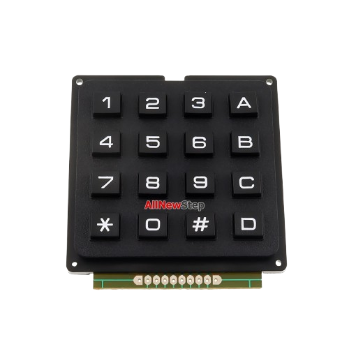
The Numpad4x4 is a 4x4 matrix keypad consisting of 16 keys arranged in a grid. It is commonly used for inputting numerical data or commands in electronic devices. Each key in the matrix is connected to a unique combination of row and column pins, allowing for efficient detection of key presses. This component is widely used in projects such as password-protected locks, calculators, and menu navigation systems.

Explore Projects Built with Numpad4x4

Use Cirkit Designer to design, explore, and prototype these projects online. Some projects support real-time simulation. Click "Open Project" to start designing instantly!
Arduino UNO-Based Interactive LED Game with 8x8 Matrix and TM1637 Display
Image of Gra_na_refleks: A project utilizing Numpad4x4 in a practical application
This circuit is a game system controlled by an Arduino UNO, featuring an 8x8 LED matrix, a 4x4 keypad, and a TM1637 4-digit display. The user interacts with the game via the keypad, and the game state is displayed on the LED matrix and the TM1637 display, with power supplied by a 9V battery.
Cirkit Designer LogoOpen Project in Cirkit Designer
Arduino UNO Based 4x4 Keypad Interface
Image of keypad: A project utilizing Numpad4x4 in a practical application
This circuit connects a 4x4 membrane matrix keypad to an Arduino UNO microcontroller. The rows (R1-R4) and columns (C1-C4) of the keypad are wired to digital pins D9-D2 on the Arduino, respectively. The purpose of the circuit is to allow the Arduino to detect and process key presses from the keypad, which can be used for user input in various applications.
Cirkit Designer LogoOpen Project in Cirkit Designer
Arduino UNO Based Calculator with LCD Display and Membrane Keypad
Image of Arduino Calculator: A project utilizing Numpad4x4 in a practical application
This circuit functions as an interactive calculator with a user interface. An Arduino UNO microcontroller is connected to a 4x4 membrane matrix keypad for input and an LCD I2C display for output. The embedded code on the Arduino handles the logic for mathematical operations entered through the keypad and displays the results on the LCD.
Cirkit Designer LogoOpen Project in Cirkit Designer
Arduino Nano-Based Dual 4x4 Keypad Interface with LCD Display and NRF24L01 Wireless Communication
Image of Sumit-radio-Reciver: A project utilizing Numpad4x4 in a practical application
This circuit features an Arduino Nano microcontroller interfaced with two 4x4 membrane matrix keypads, an NRF24L01 wireless module, and a 20x4 I2C LCD display. The keypads are connected through resistors to the Arduino for input detection, while the NRF24L01 module enables wireless communication, and the LCD display provides visual output. The setup and loop functions in the Arduino code are placeholders for further development.
Cirkit Designer LogoOpen Project in Cirkit Designer

Explore Projects Built with Numpad4x4

Use Cirkit Designer to design, explore, and prototype these projects online. Some projects support real-time simulation. Click "Open Project" to start designing instantly!
Image of Gra_na_refleks: A project utilizing Numpad4x4 in a practical application
Arduino UNO-Based Interactive LED Game with 8x8 Matrix and TM1637 Display
This circuit is a game system controlled by an Arduino UNO, featuring an 8x8 LED matrix, a 4x4 keypad, and a TM1637 4-digit display. The user interacts with the game via the keypad, and the game state is displayed on the LED matrix and the TM1637 display, with power supplied by a 9V battery.
Cirkit Designer LogoOpen Project in Cirkit Designer
Image of keypad: A project utilizing Numpad4x4 in a practical application
Arduino UNO Based 4x4 Keypad Interface
This circuit connects a 4x4 membrane matrix keypad to an Arduino UNO microcontroller. The rows (R1-R4) and columns (C1-C4) of the keypad are wired to digital pins D9-D2 on the Arduino, respectively. The purpose of the circuit is to allow the Arduino to detect and process key presses from the keypad, which can be used for user input in various applications.
Cirkit Designer LogoOpen Project in Cirkit Designer
Image of Arduino Calculator: A project utilizing Numpad4x4 in a practical application
Arduino UNO Based Calculator with LCD Display and Membrane Keypad
This circuit functions as an interactive calculator with a user interface. An Arduino UNO microcontroller is connected to a 4x4 membrane matrix keypad for input and an LCD I2C display for output. The embedded code on the Arduino handles the logic for mathematical operations entered through the keypad and displays the results on the LCD.
Cirkit Designer LogoOpen Project in Cirkit Designer
Image of Sumit-radio-Reciver: A project utilizing Numpad4x4 in a practical application
Arduino Nano-Based Dual 4x4 Keypad Interface with LCD Display and NRF24L01 Wireless Communication
This circuit features an Arduino Nano microcontroller interfaced with two 4x4 membrane matrix keypads, an NRF24L01 wireless module, and a 20x4 I2C LCD display. The keypads are connected through resistors to the Arduino for input detection, while the NRF24L01 module enables wireless communication, and the LCD display provides visual output. The setup and loop functions in the Arduino code are placeholders for further development.
Cirkit Designer LogoOpen Project in Cirkit Designer

Common Applications

  • Password-protected security systems
  • Calculators and data entry devices
  • Menu navigation in embedded systems
  • Home automation control panels
  • Robotics and IoT projects

Technical Specifications

The Numpad4x4 is a passive input device that requires external circuitry or a microcontroller to detect key presses. Below are its key specifications:

Parameter Value
Number of Keys 16 (4 rows × 4 columns)
Operating Voltage 3.3V to 5V
Keypad Dimensions ~7cm × 7cm
Interface Type Matrix (8 pins: 4 rows, 4 columns)
Keypad Material Plastic with conductive pads
Connector Type Male header pins

Pin Configuration

The Numpad4x4 has 8 pins, which are divided into 4 row pins and 4 column pins. The table below describes the pin configuration:

Pin Description
R1 Row 1
R2 Row 2
R3 Row 3
R4 Row 4
C1 Column 1
C2 Column 2
C3 Column 3
C4 Column 4

Usage Instructions

Connecting the Numpad4x4 to a Microcontroller

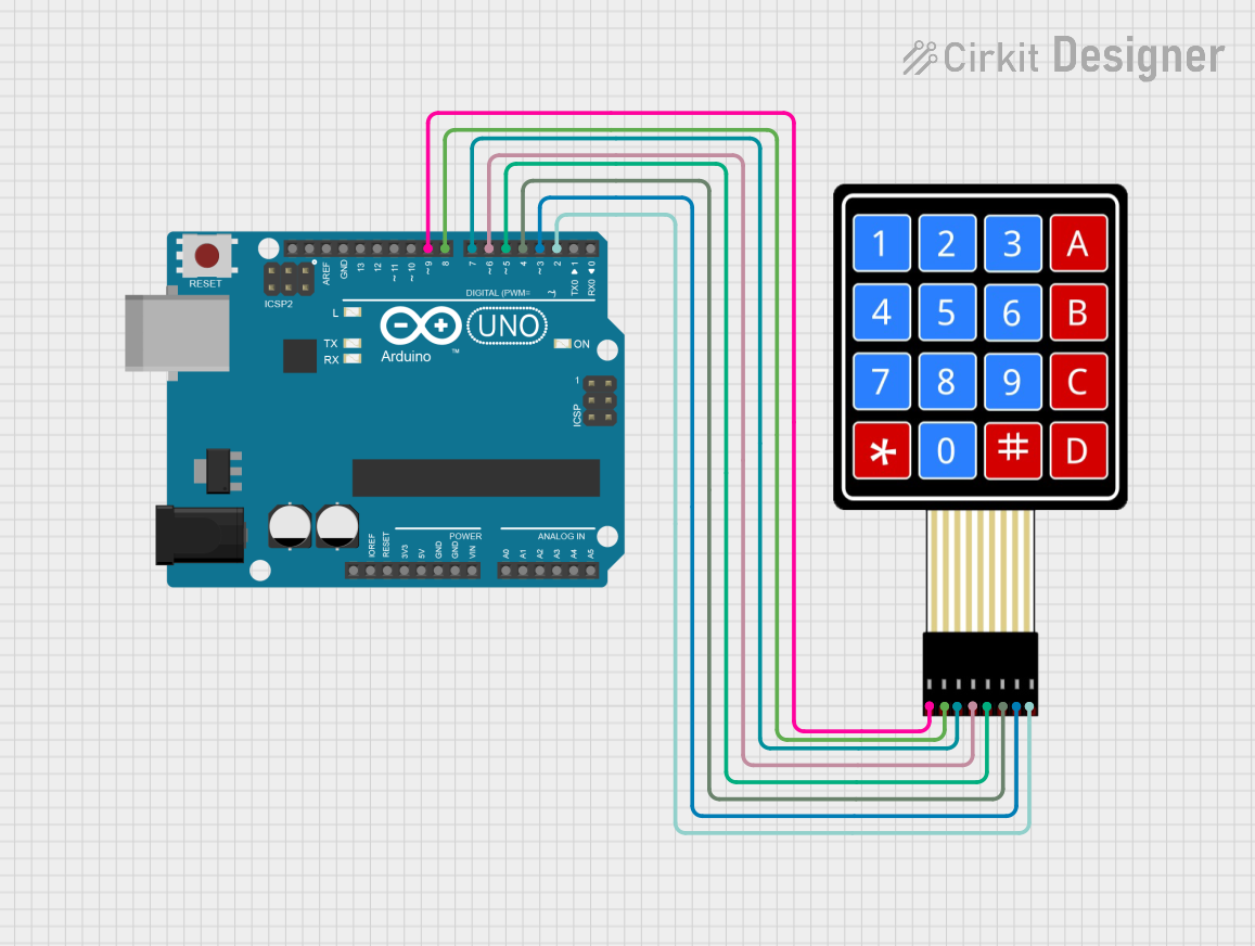
To use the Numpad4x4, connect its 8 pins to a microcontroller. The rows (R1–R4) and columns (C1–C4) are scanned to detect which key is pressed. A common approach is to use a library, such as the Arduino Keypad library, to simplify the process.

Example Circuit

  1. Connect the row pins (R1–R4) to digital input/output pins on the microcontroller.
  2. Connect the column pins (C1–C4) to additional digital input/output pins.
  3. Use pull-up or pull-down resistors if required by your microcontroller.

Sample Code for Arduino UNO

Below is an example of how to use the Numpad4x4 with an Arduino UNO:

#include <Keypad.h>

// Define the rows and columns of the keypad
const byte ROWS = 4; // Four rows
const byte COLS = 4; // Four columns

// Define the keymap for the keypad
char keys[ROWS][COLS] = {
  {'1', '2', '3', 'A'},
  {'4', '5', '6', 'B'},
  {'7', '8', '9', 'C'},
  {'*', '0', '#', 'D'}
};

// Define the row and column pins connected to the keypad
byte rowPins[ROWS] = {9, 8, 7, 6}; // Connect to R1, R2, R3, R4
byte colPins[COLS] = {5, 4, 3, 2}; // Connect to C1, C2, C3, C4

// Create a Keypad object
Keypad keypad = Keypad(makeKeymap(keys), rowPins, colPins, ROWS, COLS);

void setup() {
  Serial.begin(9600); // Initialize serial communication
  Serial.println("Numpad4x4 Test");
}

void loop() {
  char key = keypad.getKey(); // Check if a key is pressed

  if (key) {
    // Print the pressed key to the serial monitor
    Serial.print("Key Pressed: ");
    Serial.println(key);
  }
}

Best Practices

  • Use a stable power supply to avoid erratic key detection.
  • Debounce the keys in software to prevent multiple detections of a single press.
  • Avoid pressing multiple keys simultaneously, as this may cause ghosting (incorrect key detection).

Troubleshooting and FAQs

Common Issues

  1. No key press is detected:

    • Ensure all connections between the keypad and microcontroller are secure.
    • Verify that the row and column pins are correctly assigned in the code.
  2. Incorrect key is detected:

    • Check for loose or shorted connections.
    • Ensure the keymap in the code matches the physical layout of the keypad.
  3. Multiple keys are detected at once:

    • This may be caused by ghosting. Use a microcontroller with built-in pull-up resistors or add external diodes to prevent ghosting.

FAQs

Q: Can the Numpad4x4 be used with a 3.3V microcontroller?
A: Yes, the Numpad4x4 is compatible with both 3.3V and 5V systems.

Q: How do I clean the keypad if it becomes unresponsive?
A: Use a soft, dry cloth to clean the surface. Avoid using liquids, as they may damage the conductive pads.

Q: Can I use fewer than 16 keys?
A: Yes, you can modify the keymap and only use the rows and columns corresponding to the desired keys.

By following this documentation, you can effectively integrate the Numpad4x4 into your projects and troubleshoot common issues.