How to Use 555 Timer IC: Examples, Pinouts, and Specs
Introduction
The 555 Timer IC is a highly versatile integrated circuit used in a variety of timing, pulse generation, and oscillator applications. It can be configured in several modes, including monostable, astable, and bistable, each providing different functionality. This IC is popular among hobbyists and professionals due to its simplicity, low cost, and stability.
Explore Projects Built with 555 Timer IC
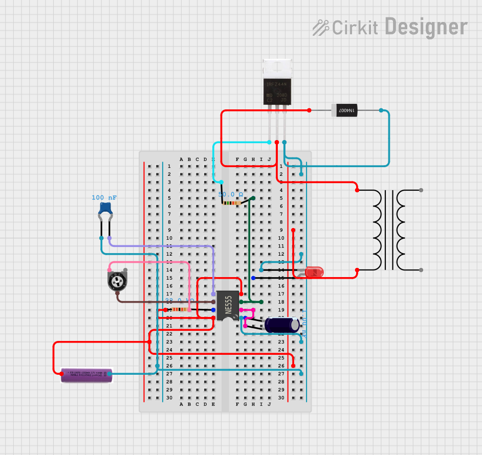
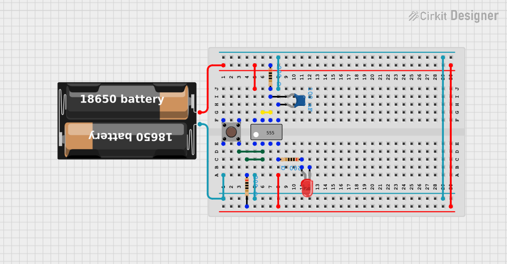
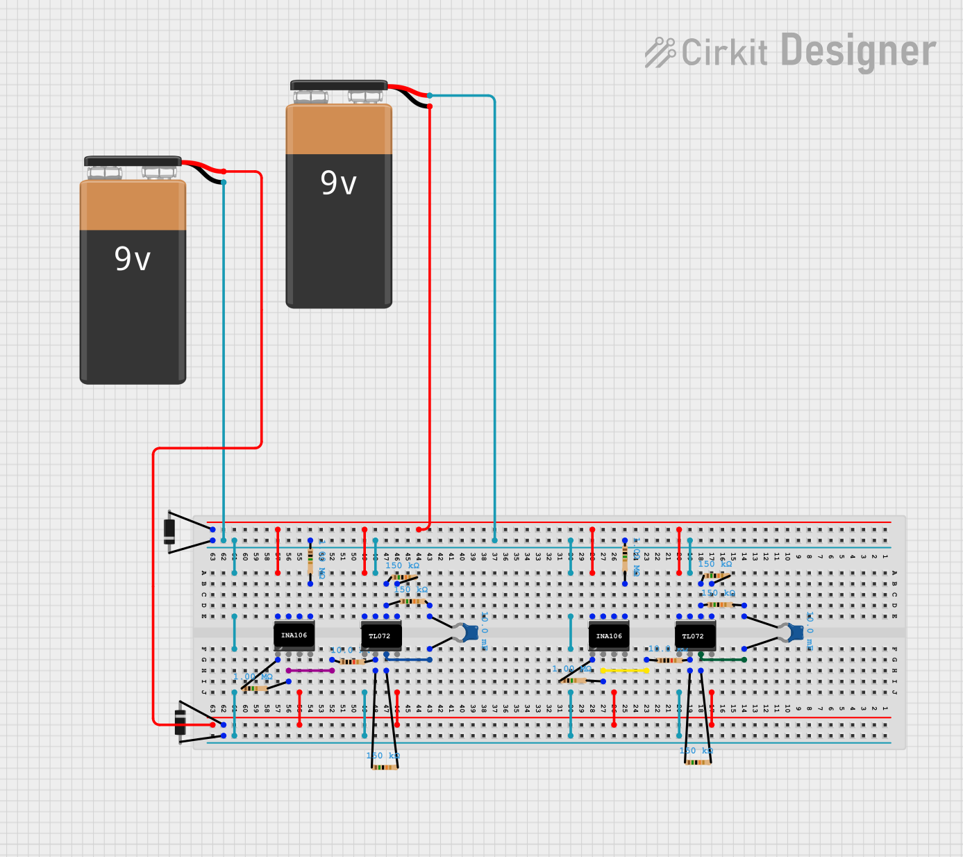
Explore Projects Built with 555 Timer IC
Common Applications and Use Cases
- Pulse generation
- Time delay circuits
- Oscillators
- PWM (Pulse Width Modulation) control
- Tone generation
Technical Specifications
Key Technical Details
- Supply Voltage (Vcc): 4.5V to 15V
- Output Current (Sink/Source): 200 mA
- Operating Temperature: -55°C to +125°C
- Timing Range: Microseconds to hours
- Package: Available in 8-pin PDIP, SOIC, and (other variants)
Pin Configuration and Descriptions
| Pin Number | Name | Description |
|---|---|---|
| 1 | GND | Ground reference voltage, low level (0V) |
| 2 | TRIG | Trigger: Activates the timer (output goes high) when voltage falls below 1/3 Vcc |
| 3 | OUT | Output: Drives the output high or low |
| 4 | RST | Reset: A low level on this pin resets the timer |
| 5 | CTRL | Control Voltage: Adjusts the threshold and trigger levels |
| 6 | THRS | Threshold: Deactivates the timer (output goes low) when voltage reaches 2/3 Vcc |
| 7 | DISCH | Discharge: Connected internally to a transistor that can discharge a capacitor between intervals |
| 8 | Vcc | Positive supply voltage |
Usage Instructions
How to Use the Component in a Circuit
Astable Mode (Oscillator):
- Connect two resistors and a capacitor to set the frequency of oscillation.
- The output will continuously switch between high and low states, creating a square wave.
Monostable Mode (One-shot):
- A single pulse is generated when the trigger pin is activated.
- The duration of the pulse is determined by the connected resistor and capacitor.
Bistable Mode (Flip-flop):
- The output changes state only when the trigger or reset pins are activated.
Important Considerations and Best Practices
- Ensure the power supply voltage is within the specified range.
- Use decoupling capacitors near the power supply pins to minimize noise.
- Avoid connecting the output directly to a high-current load; use a transistor or relay if necessary.
- For accurate timing, use high-quality resistors and capacitors with low tolerance.
Example Circuit and Code
Blinking LED with 555 Timer in Astable Mode
// Arduino code to blink an LED using a 555 Timer in astable mode
int ledPin = 13; // LED connected to digital pin 13

void setup() {
  pinMode(ledPin, OUTPUT); // sets the digital pin as output
}

void loop() {
  digitalWrite(ledPin, HIGH); // sets the LED on
  delay(1000); // waits for a second
  digitalWrite(ledPin, LOW); // sets the LED off
  delay(1000); // waits for a second
}
Note: The above code assumes the 555 Timer is configured to toggle the LED at a 1-second interval.
Troubleshooting and FAQs
Common Issues Users Might Face
- No Output: Ensure the power supply is connected properly and the IC is not damaged.
- Unstable Frequency: Check the quality of the resistors and capacitors.
- Output Stays High or Low: Verify that the trigger and threshold voltages are set correctly.
Solutions and Tips for Troubleshooting
- Double-check the pin connections and ensure they match the intended configuration.
- Replace the 555 Timer IC if it seems to be non-functional after verifying connections.
- Use an oscilloscope to check the output waveform for expected behavior.
FAQs
Q: Can the 555 Timer IC be used with a 3.3V supply? A: While the standard 555 Timer IC requires a minimum of 4.5V, there are low-voltage versions available that can operate at 3.3V.
Q: How do I calculate the frequency for astable mode?
A: The frequency can be calculated using the formula: f = 1.44 / ((R1 + 2 * R2) * C), where R1 and R2 are the resistors, and C is the capacitor in the circuit.
Q: Is it possible to sync the 555 Timer with an external clock? A: Yes, the 555 Timer can be synchronized with an external clock by applying pulses to the trigger and threshold pins.
This documentation provides a comprehensive overview of the 555 Timer IC, ensuring users can effectively incorporate it into their projects.