How to Use MKE-S02 LDR: Examples, Pinouts, and Specs
Introduction
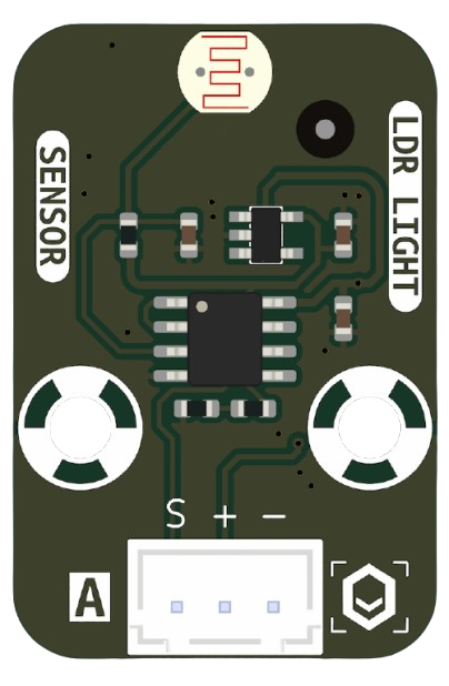
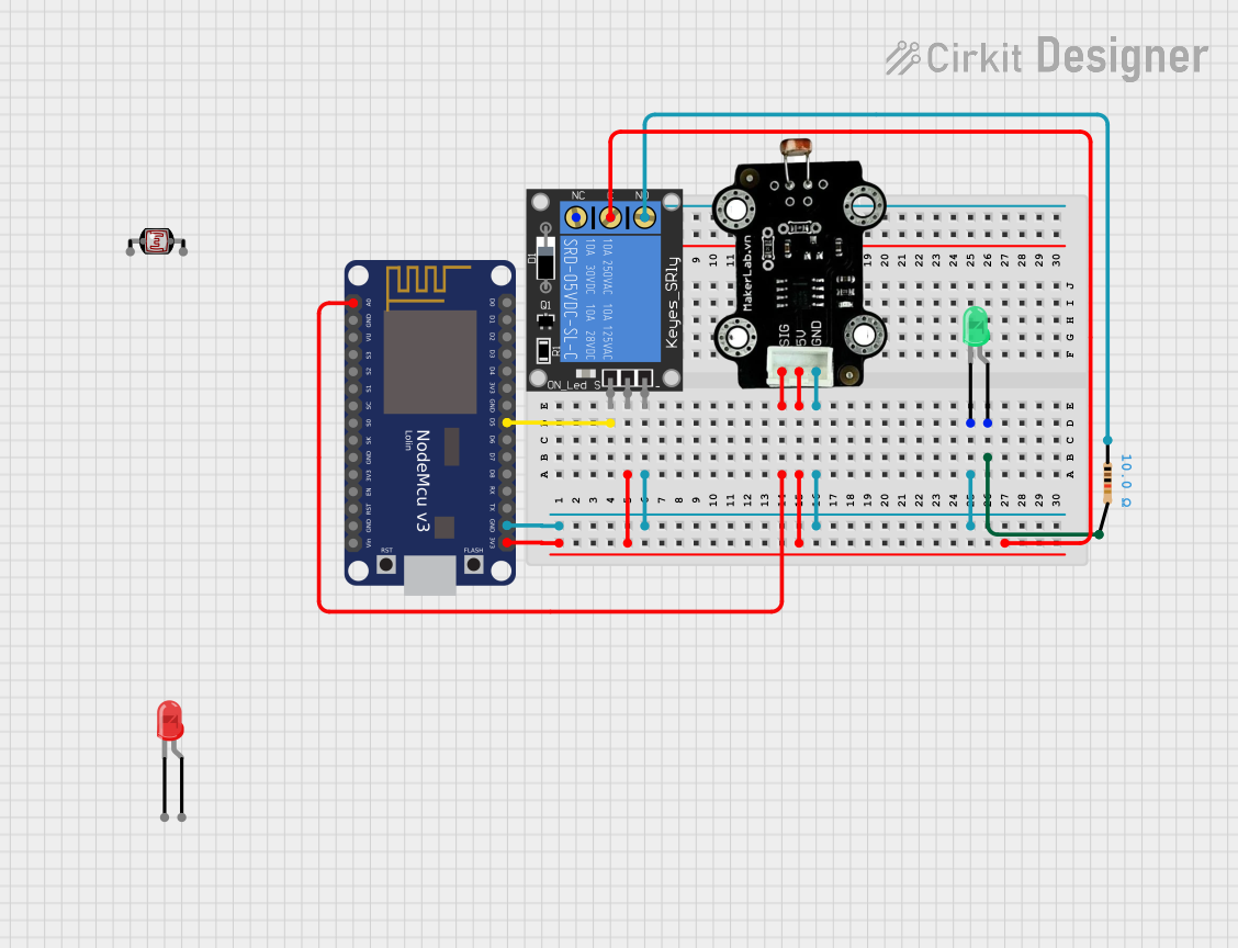
The MKE-S02 LDR (Light Dependent Resistor) is a photoresistor manufactured by MakerEdu.vn with the part ID Sensor. This component is designed to change its resistance based on the intensity of light it is exposed to. When the light intensity increases, the resistance decreases, and vice versa. This property makes it an essential component in light-sensing applications.
Explore Projects Built with MKE-S02 LDR
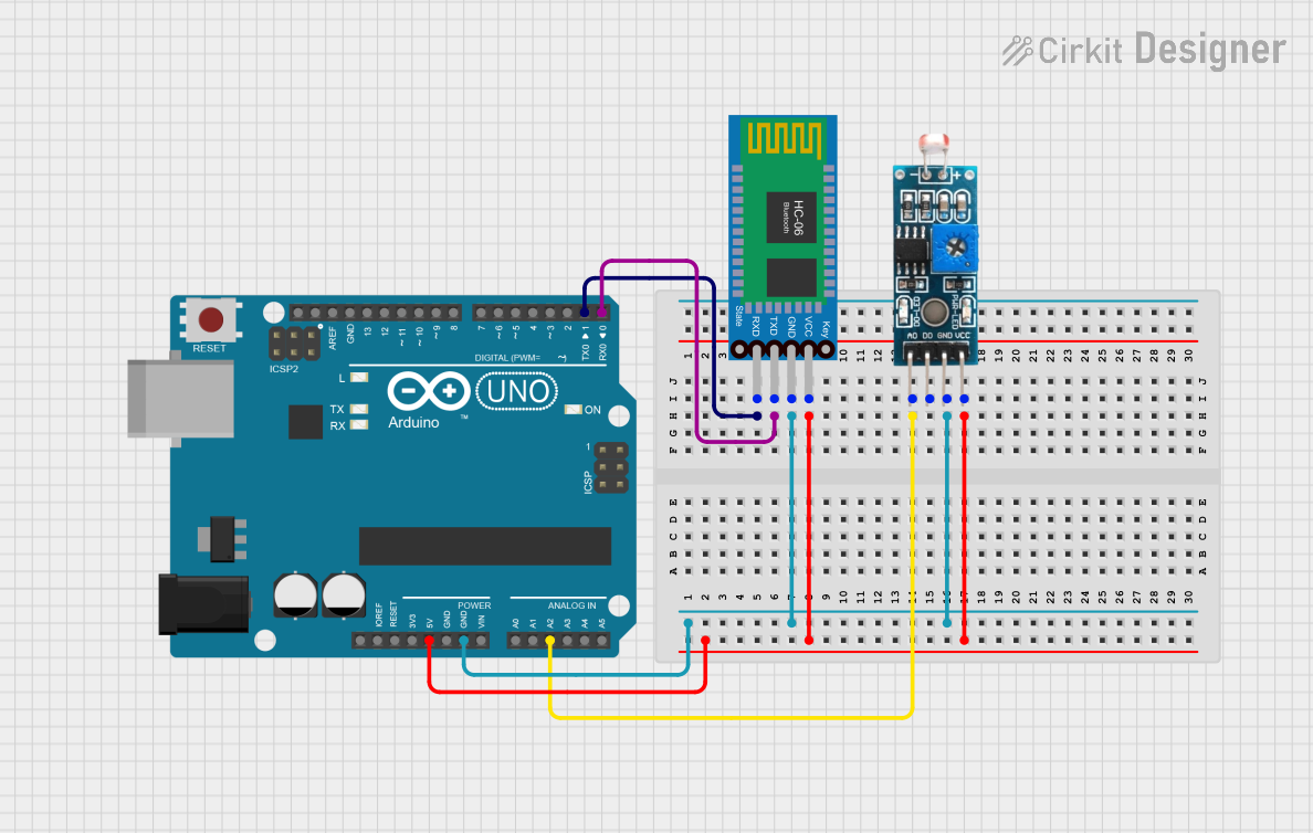
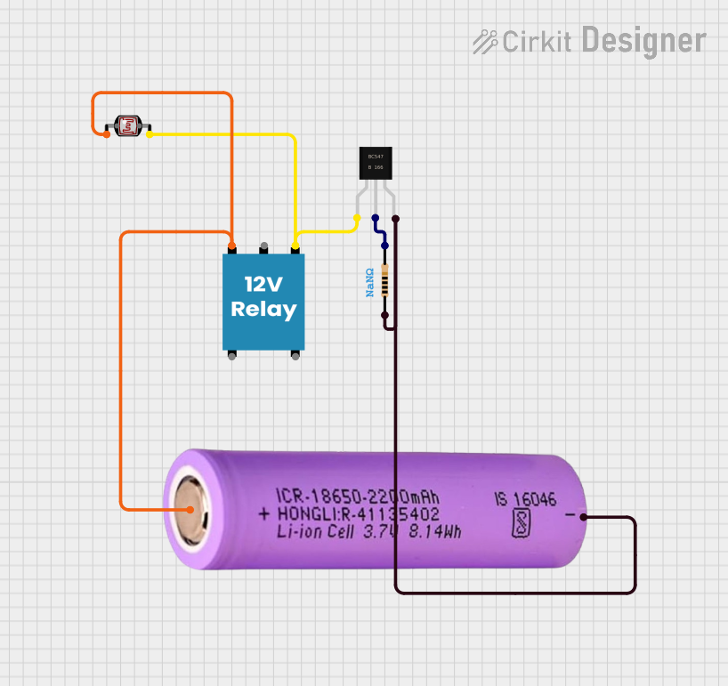
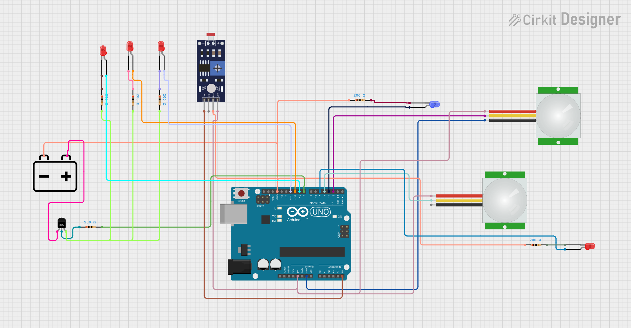
Explore Projects Built with MKE-S02 LDR
Common Applications and Use Cases
- Automatic lighting systems (e.g., streetlights that turn on at night)
- Light meters and brightness detection
- Solar tracking systems
- Alarm systems triggered by changes in light
- DIY electronics projects involving light sensing
Technical Specifications
The following table outlines the key technical details of the MKE-S02 LDR:
| Parameter | Value |
|---|---|
| Manufacturer | MakerEdu.vn |
| Part ID | Sensor |
| Resistance (Dark) | 1 MΩ (typical) |
| Resistance (Bright) | 10 kΩ (typical, under bright light) |
| Operating Voltage | 3.3V to 5V |
| Power Dissipation | 100 mW (maximum) |
| Response Time (Rise) | 20 ms |
| Response Time (Fall) | 30 ms |
| Operating Temperature | -30°C to +70°C |
| Dimensions | 5 mm diameter |
Pin Configuration and Descriptions
The MKE-S02 LDR is a two-terminal device. The pins are not polarized, meaning it can be connected in either orientation. Below is a description of the pins:
| Pin | Description |
|---|---|
| Pin 1 | Connects to the positive side of the circuit (e.g., voltage divider) |
| Pin 2 | Connects to the negative side of the circuit (e.g., ground or resistor) |
Usage Instructions
How to Use the MKE-S02 LDR in a Circuit
The MKE-S02 LDR is typically used in a voltage divider circuit to convert changes in light intensity into a measurable voltage. Below is a step-by-step guide:
Connect the LDR in Series with a Resistor:
- Choose a resistor value (e.g., 10 kΩ) based on the desired sensitivity.
- Connect one terminal of the LDR to the positive voltage supply (e.g., 5V).
- Connect the other terminal of the LDR to one terminal of the resistor.
- Connect the other terminal of the resistor to ground.
Measure the Voltage:
- The voltage at the junction between the LDR and the resistor will vary based on the light intensity.
- Connect this junction to an analog input pin of a microcontroller (e.g., Arduino UNO) to read the voltage.
Write Code to Process the Signal:
- Use the analog-to-digital converter (ADC) of the microcontroller to read the voltage and interpret the light intensity.
Important Considerations and Best Practices
- Resistor Selection: The value of the series resistor affects the sensitivity of the circuit. Experiment with different resistor values to achieve the desired response.
- Ambient Light: Ensure the LDR is shielded from unwanted light sources if precise measurements are required.
- Voltage Range: Operate the LDR within the specified voltage range (3.3V to 5V) to avoid damage.
- Response Time: Note that the LDR has a slight delay in response to changes in light intensity (20-30 ms).
Example Code for Arduino UNO
Below is an example of how to use the MKE-S02 LDR with an Arduino UNO to measure light intensity:
// Define the analog pin connected to the LDR
const int ldrPin = A0; // LDR connected to analog pin A0

void setup() {
  Serial.begin(9600); // Initialize serial communication at 9600 baud
}

void loop() {
  int ldrValue = analogRead(ldrPin); // Read the analog value from the LDR
  float voltage = ldrValue * (5.0 / 1023.0); // Convert ADC value to voltage

  // Print the light intensity (as voltage) to the Serial Monitor
  Serial.print("Light Intensity (Voltage): ");
  Serial.println(voltage);

  delay(500); // Wait for 500 ms before the next reading
}
Notes on the Code
- The
analogRead()function reads the voltage at the LDR-resistor junction and converts it to a digital value (0-1023). - The voltage is calculated using the formula:
voltage = ADC_value * (Vcc / 1023), whereVccis the supply voltage (5V for Arduino UNO). - The delay of 500 ms ensures the readings are updated at regular intervals.
Troubleshooting and FAQs
Common Issues and Solutions
No Change in Voltage Readings:
- Cause: Incorrect wiring or loose connections.
- Solution: Double-check the connections and ensure the LDR is properly connected in series with the resistor.
Inconsistent Readings:
- Cause: Electrical noise or interference.
- Solution: Use a capacitor (e.g., 0.1 µF) across the LDR to filter out noise.
LDR Not Responding to Light Changes:
- Cause: LDR damaged or exposed to extreme conditions.
- Solution: Replace the LDR and ensure it is operated within the specified temperature and voltage ranges.
Low Sensitivity:
- Cause: Incorrect resistor value in the voltage divider.
- Solution: Experiment with different resistor values to optimize sensitivity.
FAQs
Q1: Can the MKE-S02 LDR detect infrared light?
A1: The MKE-S02 LDR is primarily sensitive to visible light. It may have limited sensitivity to infrared light, but it is not designed for precise IR detection.
Q2: Can I use the MKE-S02 LDR with a 3.3V microcontroller?
A2: Yes, the LDR operates within a voltage range of 3.3V to 5V, making it compatible with 3.3V systems.
Q3: How do I protect the LDR from environmental damage?
A3: Use a transparent enclosure or coating to shield the LDR from moisture, dust, and physical damage while allowing light to pass through.
Q4: What is the lifespan of the MKE-S02 LDR?
A4: The MKE-S02 LDR has a long lifespan if operated within its specified limits. Avoid exposing it to extreme temperatures or voltages to ensure durability.