Cirkit Designer Logo
Cirkit Designer
Your all-in-one circuit design IDE
Home / 
Component Documentation

How to Use cytron: Examples, Pinouts, and Specs

Image of cytron
Cirkit Designer LogoDesign with cytron in Cirkit Designer

Introduction

Cytron Technologies is a company that specializes in creating electronic components for robotics and automation projects. Among their products, motor drivers are some of the most prominent and widely used. These drivers are essential for controlling the speed, direction, and torque of motors in various applications, from hobbyist projects to industrial automation systems.

Explore Projects Built with cytron

Use Cirkit Designer to design, explore, and prototype these projects online. Some projects support real-time simulation. Click "Open Project" to start designing instantly!
Battery-Powered Line Following Robot with IR Sensors and Cytron URC10 Motor Controller
Image of URC10 SUMO AUTO: A project utilizing cytron in a practical application
This circuit is a robotic control system that uses multiple IR sensors for line detection and obstacle avoidance, powered by a 3S LiPo battery. The Cytron URC10 motor driver, controlled by a microcontroller, drives two GM25 DC motors based on input from the sensors and a rocker switch, with a 7-segment panel voltmeter displaying the battery voltage.
Cirkit Designer LogoOpen Project in Cirkit Designer
Arduino-Controlled Motor System with Bluetooth Connectivity
Image of mine_1: A project utilizing cytron in a practical application
This is a motor control system with wireless communication capabilities, designed to operate multiple motors via Cytron motor drivers, controlled by Arduino UNOs. It includes relays for activating a light and buzzer, and uses Bluetooth for remote operation. The system's software is in the initial stages of development.
Cirkit Designer LogoOpen Project in Cirkit Designer
Raspberry Pi 5-Controlled Robotics Platform with IR Obstacle Detection and Camera
Image of forklift circuit diagram 1: A project utilizing cytron in a practical application
This is a motor control system for multiple DC motors, utilizing Cytron and L298N motor drivers for speed and direction control. It is managed by a Raspberry Pi 5, which also interfaces with IR sensors for object detection and a camera for image capture, indicating potential use in robotics or automated systems.
Cirkit Designer LogoOpen Project in Cirkit Designer
Arduino UNO and Cytron Motor Driver Controlled Two-Wheel Mobile Robot
Image of Power Window with Motor Driver & Arduino: A project utilizing cytron in a practical application
This circuit is a control system for a two-wheel mobile robot, utilizing an Arduino UNO to manage a Cytron motor driver. The Arduino controls the direction and speed of two power window motors via PWM and direction signals, powered by a LiPo battery.
Cirkit Designer LogoOpen Project in Cirkit Designer

Explore Projects Built with cytron

Use Cirkit Designer to design, explore, and prototype these projects online. Some projects support real-time simulation. Click "Open Project" to start designing instantly!
Image of URC10 SUMO AUTO: A project utilizing cytron in a practical application
Battery-Powered Line Following Robot with IR Sensors and Cytron URC10 Motor Controller
This circuit is a robotic control system that uses multiple IR sensors for line detection and obstacle avoidance, powered by a 3S LiPo battery. The Cytron URC10 motor driver, controlled by a microcontroller, drives two GM25 DC motors based on input from the sensors and a rocker switch, with a 7-segment panel voltmeter displaying the battery voltage.
Cirkit Designer LogoOpen Project in Cirkit Designer
Image of mine_1: A project utilizing cytron in a practical application
Arduino-Controlled Motor System with Bluetooth Connectivity
This is a motor control system with wireless communication capabilities, designed to operate multiple motors via Cytron motor drivers, controlled by Arduino UNOs. It includes relays for activating a light and buzzer, and uses Bluetooth for remote operation. The system's software is in the initial stages of development.
Cirkit Designer LogoOpen Project in Cirkit Designer
Image of forklift circuit diagram 1: A project utilizing cytron in a practical application
Raspberry Pi 5-Controlled Robotics Platform with IR Obstacle Detection and Camera
This is a motor control system for multiple DC motors, utilizing Cytron and L298N motor drivers for speed and direction control. It is managed by a Raspberry Pi 5, which also interfaces with IR sensors for object detection and a camera for image capture, indicating potential use in robotics or automated systems.
Cirkit Designer LogoOpen Project in Cirkit Designer
Image of Power Window with Motor Driver & Arduino: A project utilizing cytron in a practical application
Arduino UNO and Cytron Motor Driver Controlled Two-Wheel Mobile Robot
This circuit is a control system for a two-wheel mobile robot, utilizing an Arduino UNO to manage a Cytron motor driver. The Arduino controls the direction and speed of two power window motors via PWM and direction signals, powered by a LiPo battery.
Cirkit Designer LogoOpen Project in Cirkit Designer

Common Applications and Use Cases

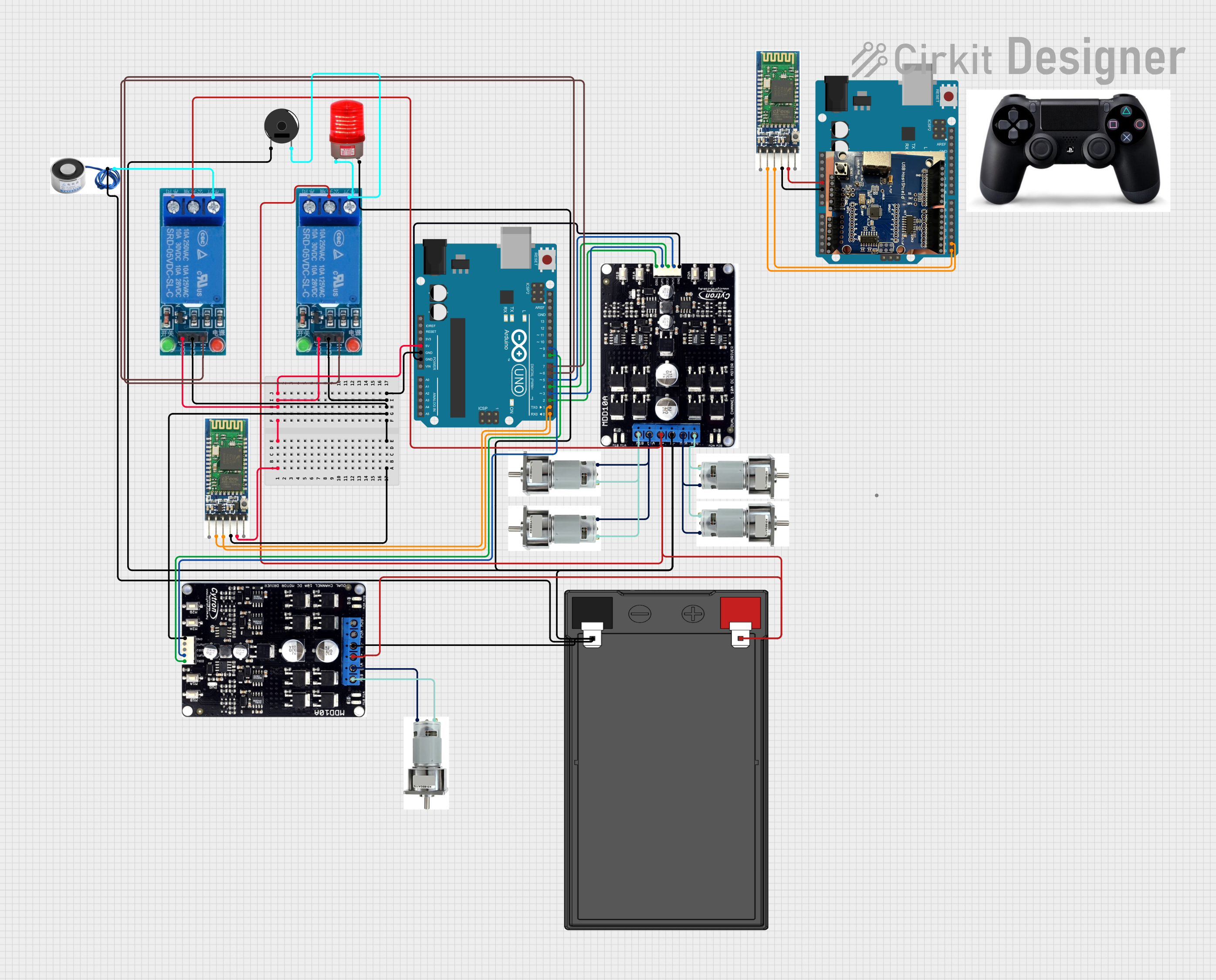
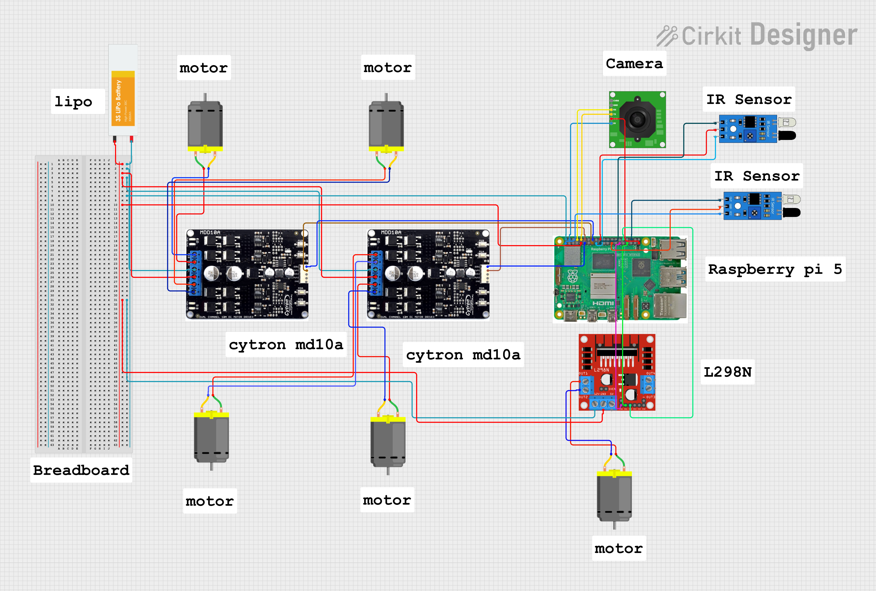
  • Robotics: Controlling DC, stepper, or servo motors for movement and positioning.
  • Automation: Driving conveyor belts, actuators, and other machinery.
  • Educational Projects: Used in teaching electronics and robotics.
  • Hobby Projects: DIY projects such as remote-controlled vehicles and home automation.

Technical Specifications

Key Technical Details

  • Voltage Range: Typically from 5V to 30V, depending on the model.
  • Current Rating: Varies, with some models supporting up to several amps of continuous current.
  • Power Ratings: Dependent on voltage and current specifications.

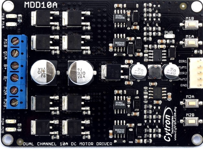
Pin Configuration and Descriptions

Pin Name Description
VCC Power supply for the motor driver (5V to 30V)
GND Ground connection
IN1 Input control pin 1
IN2 Input control pin 2
PWM Pulse Width Modulation input for speed control
OUT1 Output to motor terminal A
OUT2 Output to motor terminal B

Note: The actual pin configuration may vary depending on the specific Cytron motor driver model. Always refer to the datasheet of the specific model you are using.

Usage Instructions

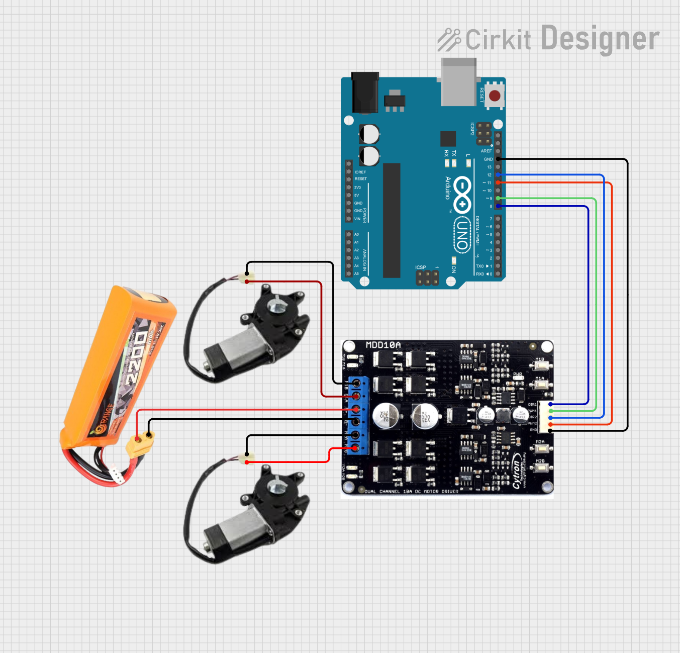
How to Use the Component in a Circuit

  1. Connect the motor terminals to the OUT1 and OUT2 pins.
  2. Supply the motor voltage to the VCC pin and connect the ground.
  3. Apply control signals to IN1 and IN2 to set the motor direction.
  4. Use the PWM pin to control the speed of the motor by varying the duty cycle.

Important Considerations and Best Practices

  • Ensure the power supply matches the motor driver's voltage requirements.
  • Do not exceed the current rating of the motor driver.
  • Use appropriate decoupling capacitors to minimize voltage spikes.
  • Implement proper heat dissipation techniques if the driver is expected to handle high currents.

Example Connection with Arduino UNO

// Example code to control a Cytron motor driver with an Arduino UNO

const int in1Pin = 2; // IN1 connected to digital pin 2
const int in2Pin = 3; // IN2 connected to digital pin 3
const int pwmPin = 5; // PWM connected to digital pin 5 (supports PWM)

void setup() {
  pinMode(in1Pin, OUTPUT);
  pinMode(in2Pin, OUTPUT);
  pinMode(pwmPin, OUTPUT);
}

void loop() {
  // Set motor direction to clockwise
  digitalWrite(in1Pin, HIGH);
  digitalWrite(in2Pin, LOW);
  
  // Set motor speed (0 to 255)
  analogWrite(pwmPin, 128); // 50% duty cycle for half speed
  
  delay(2000); // Run for 2 seconds
  
  // Change motor direction to counter-clockwise
  digitalWrite(in1Pin, LOW);
  digitalWrite(in2Pin, HIGH);
  
  delay(2000); // Run for 2 seconds
  
  // Stop the motor
  digitalWrite(in1Pin, LOW);
  digitalWrite(in2Pin, LOW);
  
  delay(2000); // Stop for 2 seconds
}

Note: The above code is a simple demonstration. Adjust the pin numbers and logic according to your specific application and motor driver model.

Troubleshooting and FAQs

Common Issues Users Might Face

  • Motor not running: Check power supply, connections, and signals to IN1, IN2, and PWM.
  • Motor running hot: Ensure the current does not exceed the driver's rating and improve cooling.
  • Inconsistent motor speed: Verify PWM signal and power supply stability.

Solutions and Tips for Troubleshooting

  • Double-check wiring and solder joints for any loose connections.
  • Use a multimeter to verify the voltage levels at VCC and the PWM signal.
  • Implement a gradual start/stop in your code to avoid sudden current spikes.

FAQs

Q: Can I control two motors with one Cytron driver? A: Some Cytron drivers support dual channels for controlling two motors. Check the specific model's datasheet.

Q: What is the maximum frequency for the PWM signal? A: This depends on the specific motor driver model. Refer to the datasheet for the maximum PWM frequency.

Q: How do I reverse the motor direction? A: Swap the logic levels on IN1 and IN2 pins to reverse the motor's direction.

Note: Always consult the datasheet of the specific Cytron motor driver model you are using for accurate information and instructions.