How to Use rp2040 zero: Examples, Pinouts, and Specs

Introduction
The RP2040 Zero is a compact microcontroller unit (MCU) based on the RP2040 microcontroller chip developed by Raspberry Pi. It is designed for hobbyists, educators, and professionals who require a low-cost, high-performance microcontroller for embedded projects. The RP2040 Zero is particularly well-suited for applications such as robotics, IoT devices, wearables, and DIY electronics due to its small form factor and powerful dual-core ARM Cortex-M0+ processor.
Explore Projects Built with rp2040 zero
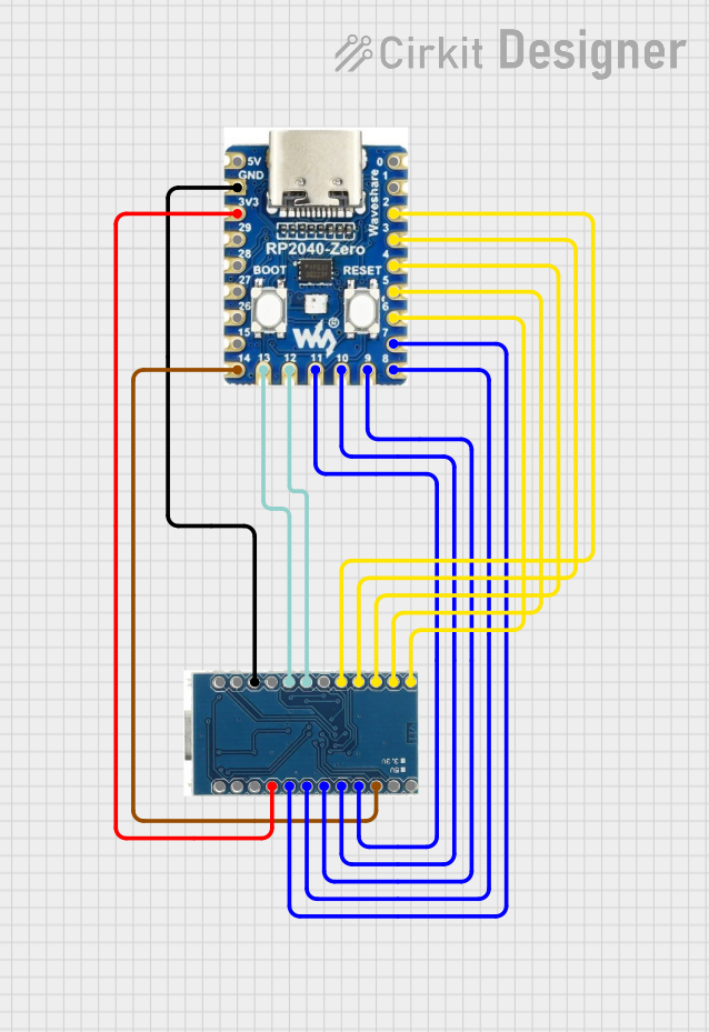
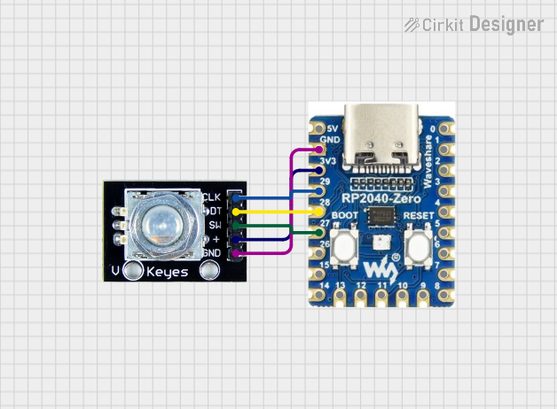

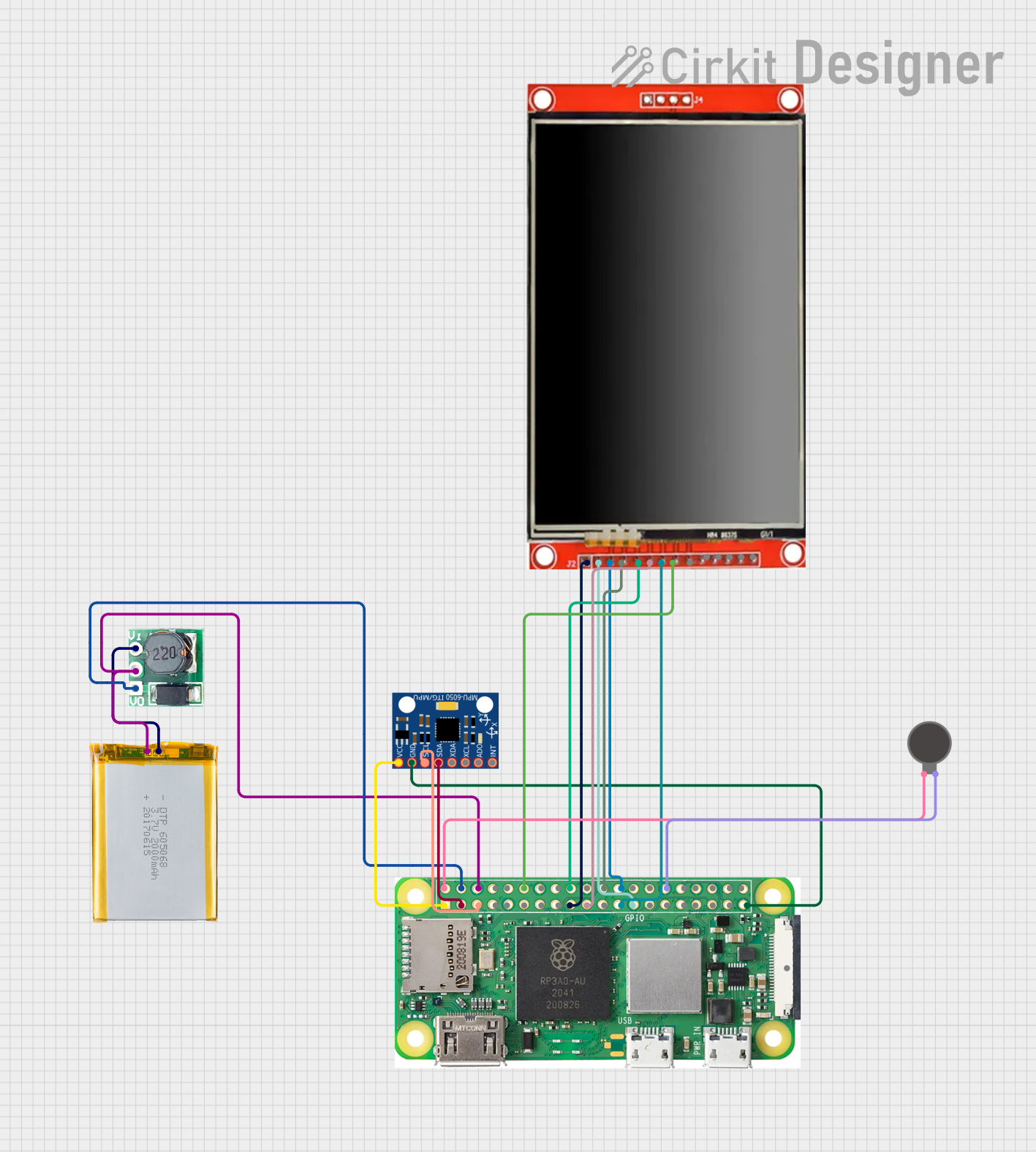
Explore Projects Built with rp2040 zero
Technical Specifications
Key Features
- Dual-core ARM Cortex-M0+ processor, up to 133 MHz
- 264KB of SRAM, and 2MB of on-board Flash memory
- 26 multifunction GPIO pins
- 2 × UART, 2 × SPI, 2 × I2C, 16 × PWM channels
- USB 1.1 with device and host support
- Low-power sleep and dormant modes
- Drag-and-drop programming using mass storage over USB
- 3.3V operating voltage
- Comprehensive SDK, software examples, and documentation
Pin Configuration
| Pin Number | Function | Description |
|---|---|---|
| 1 | GP0 | GPIO0, can also be used for UART, SPI, etc. |
| 2 | GP1 | GPIO1, can also be used for UART, SPI, etc. |
| ... | ... | ... |
| 26 | GP25 | GPIO25, can also be used for PWM, I2C, etc. |
| VBUS | USB VBUS | USB input voltage |
| VSYS | System Voltage | Regulated power supply input |
| 3V3 | 3.3V Out | 3.3V power output |
| GND | Ground | Ground connection |
Note: This table is not exhaustive. Refer to the RP2040 datasheet for the complete pinout and alternate functions.
Usage Instructions
Integration into a Circuit
To use the RP2040 Zero in a circuit:
- Connect the power supply to the
VSYSandGNDpins, ensuring that the voltage is within the recommended range (4.5V to 5.5V). - Interface with peripherals using the GPIO pins. Configure the pins according to the desired communication protocol (UART, SPI, I2C, etc.).
- If USB functionality is required, connect the
VBUSpin to a 5V USB power source.
Programming the RP2040 Zero
The RP2040 Zero can be programmed using C/C++ SDK or the MicroPython language. For Arduino enthusiasts, it can also be programmed using the Arduino IDE with an appropriate board support package.
Example: Blinking an LED using MicroPython
Import required module
from machine import Pin, Timer
Configure an LED on GPIO 25 (built-in LED on some boards)
led = Pin(25, Pin.OUT)
Toggle the LED state
def toggle_led(timer): led.toggle()
Create a software timer that calls the toggle_led function every 500ms
timer = Timer() timer.init(freq=2, mode=Timer.PERIODIC, callback=toggle_led)
*Note: This code assumes that MicroPython is already installed on the RP2040 Zero.*
Best Practices
- Always ensure that the power supply is within the specified range to prevent damage.
- Use proper decoupling capacitors close to the power pins to minimize power supply noise.
- Avoid exposing the board to static electricity and physical stress.
- When interfacing with other components, ensure that the voltage levels are compatible.
Troubleshooting and FAQs
Common Issues
- RP2040 Zero not recognized by the computer: Ensure that the USB cable is properly connected and that it is not a charge-only cable.
- GPIO not functioning as expected: Verify that the pin configuration in your code matches the physical connections in your circuit.
FAQs
Q: Can I power the RP2040 Zero directly from a battery?
A: Yes, you can power it using a battery connected to the VSYS pin, provided the voltage is within the recommended range.
Q: How do I reset the RP2040 Zero?
A: You can reset the board by momentarily connecting the RUN pin to GND.
Q: Is the RP2040 Zero compatible with Raspberry Pi HATs? A: No, the form factor and pinout are different. However, you can interface with HATs using jumper wires and ensuring proper voltage levels.
For further assistance, consult the RP2040 datasheet and the community forums dedicated to Raspberry Pi and RP2040-based projects.