Cirkit Designer Logo
Cirkit Designer
Your all-in-one circuit design IDE
Home / 
Component Documentation

How to Use SIM800c GSM Module: Examples, Pinouts, and Specs

Image of SIM800c GSM Module
Cirkit Designer LogoDesign with SIM800c GSM Module in Cirkit Designer

Introduction

The SIM800c GSM Module is a versatile and compact electronic component that provides GSM/GPRS communication capabilities to embedded systems. It enables devices to make phone calls, send and receive SMS messages, and connect to the internet through GPRS. This module is widely used in various applications such as remote data logging, security systems, automotive and mobile applications.

Explore Projects Built with SIM800c GSM Module

Use Cirkit Designer to design, explore, and prototype these projects online. Some projects support real-time simulation. Click "Open Project" to start designing instantly!
Arduino UNO and SIM800L SMS Communication System
Image of GSM MODULE: A project utilizing SIM800c GSM Module in a practical application
This circuit consists of an Arduino UNO connected to a SIM 800L GSM module. The Arduino UNO communicates with the SIM 800L module via software serial to send and receive SMS messages, with the Arduino providing power and ground connections to the GSM module.
Cirkit Designer LogoOpen Project in Cirkit Designer
Arduino UNO and SIM800L GSM Module for Wireless Communication with LM2596 Power Regulation
Image of theft: A project utilizing SIM800c GSM Module in a practical application
This circuit features an Arduino UNO microcontroller interfaced with a SIM 800L GSM module for communication purposes. The SIM 800L is powered by an LM2596 step-down module, which provides the necessary voltage regulation. The Arduino communicates with the SIM 800L via digital pins D2 and D3 for RX and TX respectively.
Cirkit Designer LogoOpen Project in Cirkit Designer
Arduino Nano-Based GPS Tracker with GSM Communication and IR Obstacle Detection
Image of circuit1: A project utilizing SIM800c GSM Module in a practical application
This circuit features an Arduino Nano interfaced with a SIM800L EVB GSM module for cellular communication, a GPS NEO 6M module for location tracking, and three TCRT 5000 IR sensors for object detection or line tracking. The Arduino facilitates data exchange between the GPS and GSM modules and processes signals from the IR sensors. The provided code skeleton suggests that the Arduino is programmed to perform tasks in a loop, but specific functionality is not detailed in the code.
Cirkit Designer LogoOpen Project in Cirkit Designer
Arduino Nano-Controlled GSM Relay System
Image of Arduino Nano GSM 2024: A project utilizing SIM800c GSM Module in a practical application
This circuit features an Arduino Nano microcontroller interfaced with a SIM800L GSM module and a 4-channel 5V relay module. The Arduino controls the relay channels via digital pins D4 to D7 and communicates with the SIM800L module through serial communication using pins D2 and D3. A USB power source provides power to the circuit, with an electrolytic capacitor likely used for voltage smoothing.
Cirkit Designer LogoOpen Project in Cirkit Designer

Explore Projects Built with SIM800c GSM Module

Use Cirkit Designer to design, explore, and prototype these projects online. Some projects support real-time simulation. Click "Open Project" to start designing instantly!
Image of GSM MODULE: A project utilizing SIM800c GSM Module in a practical application
Arduino UNO and SIM800L SMS Communication System
This circuit consists of an Arduino UNO connected to a SIM 800L GSM module. The Arduino UNO communicates with the SIM 800L module via software serial to send and receive SMS messages, with the Arduino providing power and ground connections to the GSM module.
Cirkit Designer LogoOpen Project in Cirkit Designer
Image of theft: A project utilizing SIM800c GSM Module in a practical application
Arduino UNO and SIM800L GSM Module for Wireless Communication with LM2596 Power Regulation
This circuit features an Arduino UNO microcontroller interfaced with a SIM 800L GSM module for communication purposes. The SIM 800L is powered by an LM2596 step-down module, which provides the necessary voltage regulation. The Arduino communicates with the SIM 800L via digital pins D2 and D3 for RX and TX respectively.
Cirkit Designer LogoOpen Project in Cirkit Designer
Image of circuit1: A project utilizing SIM800c GSM Module in a practical application
Arduino Nano-Based GPS Tracker with GSM Communication and IR Obstacle Detection
This circuit features an Arduino Nano interfaced with a SIM800L EVB GSM module for cellular communication, a GPS NEO 6M module for location tracking, and three TCRT 5000 IR sensors for object detection or line tracking. The Arduino facilitates data exchange between the GPS and GSM modules and processes signals from the IR sensors. The provided code skeleton suggests that the Arduino is programmed to perform tasks in a loop, but specific functionality is not detailed in the code.
Cirkit Designer LogoOpen Project in Cirkit Designer
Image of Arduino Nano GSM 2024: A project utilizing SIM800c GSM Module in a practical application
Arduino Nano-Controlled GSM Relay System
This circuit features an Arduino Nano microcontroller interfaced with a SIM800L GSM module and a 4-channel 5V relay module. The Arduino controls the relay channels via digital pins D4 to D7 and communicates with the SIM800L module through serial communication using pins D2 and D3. A USB power source provides power to the circuit, with an electrolytic capacitor likely used for voltage smoothing.
Cirkit Designer LogoOpen Project in Cirkit Designer

Common Applications and Use Cases

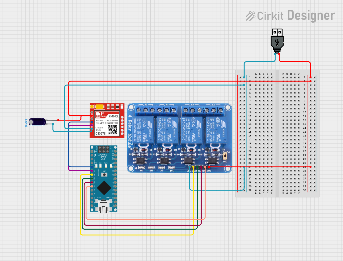
  • Remote monitoring and control systems
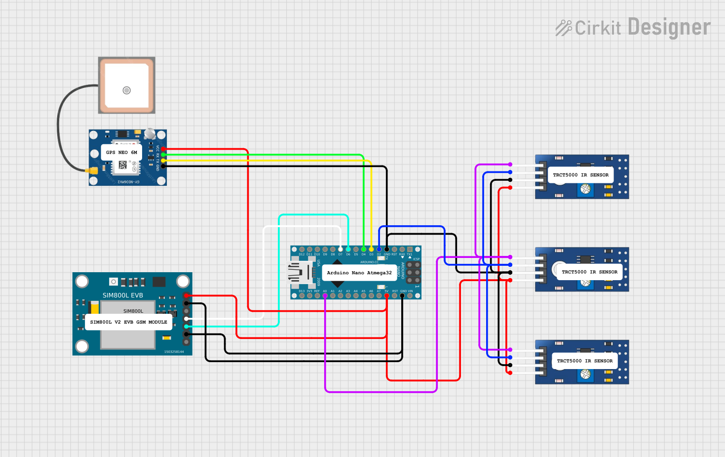
  • Vehicle tracking with GPS data transmission
  • SMS-based remote alerts and automation
  • IoT devices requiring cellular network connectivity
  • Emergency call systems

Technical Specifications

Key Technical Details

  • Frequency Bands: Quad-band 850/900/1800/1900MHz
  • GPRS Data: Downlink/uplink transfer: max 85.6 kbps
  • Transmission Power:
    • Class 4 (2W) for GSM850 and EGSM900
    • Class 1 (1W) for GSM1800 and GSM1900
  • Power Supply: 3.4V - 4.4V (Typical 4.0V)
  • Operating Temperature: -40°C to +85°C

Pin Configuration and Descriptions

Pin Number Name Description
1 VCC Power supply input (3.4V - 4.4V)
2 RST Module reset (active low)
3 RXD Serial data receive pin
4 TXD Serial data transmit pin
5 GND Ground connection
6 RI Ring indicator (active low)
7 DTR Data Terminal Ready control pin (active low)
8 CTS Clear to Send, flow control pin (active low)
9 RTS Request to Send, flow control pin (active high)
10 MIC+ Positive microphone input for voice calls
11 MIC- Negative microphone input for voice calls
12 SPK+ Positive speaker output for voice calls
13 SPK- Negative speaker output for voice calls

Usage Instructions

How to Use the Component in a Circuit

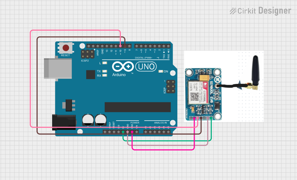
  1. Power Supply: Connect a stable power source to the VCC and GND pins. Ensure that the voltage is within the specified range.
  2. Serial Communication: Connect the RXD and TXD pins to the corresponding TX and RX pins of your microcontroller or UART interface.
  3. SIM Card: Insert a SIM card into the SIM card holder of the SIM800c module.
  4. Antenna: Attach a GSM antenna to the module to ensure proper signal reception and transmission.
  5. Audio (Optional): If voice functionality is required, connect a microphone and speaker to the MIC+/- and SPK+/- pins, respectively.

Important Considerations and Best Practices

  • Always use a regulated power supply to prevent damage to the module.
  • Ensure that the antenna is properly connected before powering up the module.
  • Use level shifters if the microcontroller operates at a different logic level than the module.
  • Follow ESD precautions when handling the module to avoid static damage.

Example Code for Arduino UNO

#include <SoftwareSerial.h>

SoftwareSerial sim800c(7, 8); // RX, TX

void setup() {
  // Begin serial communication with Arduino and Arduino IDE (Serial Monitor)
  Serial.begin(9600);
  
  // Begin serial communication with SIM800c and set baud rate
  sim800c.begin(9600);
  
  // Set module to SMS mode
  sim800c.println("AT+CMGF=1\r");
  delay(1000);
  
  // Set module to receive SMS in text mode
  sim800c.println("AT+CNMI=1,2,0,0,0\r");
  delay(1000);
}

void loop() {
  // Check if the SIM800c module is sending a message
  if (sim800c.available()) {
    Serial.write(sim800c.read());
  }
  
  // Check if the Serial Monitor is sending a message
  if (Serial.available()) {
    sim800c.write(Serial.read());
  }
}

Troubleshooting and FAQs

Common Issues Users Might Face

  • Power Issues: If the module does not power up, check the power supply and connections.
  • Signal Issues: Poor signal quality can affect communication. Ensure the antenna is properly connected and positioned.
  • SIM Card Issues: If the module cannot connect to the network, verify that the SIM card is active and properly inserted.

Solutions and Tips for Troubleshooting

  • Power Supply: Use a multimeter to verify the voltage at the VCC pin.
  • Signal Strength: Use the AT command AT+CSQ to check the signal quality.
  • SIM Card: Ensure the SIM card has no PIN code or use the AT command AT+CPIN to enter the PIN.

FAQs

Q: Can the SIM800c module connect to a 5V logic microcontroller directly? A: No, a level shifter is recommended to convert the 5V logic level to the 3.3V level required by the SIM800c module.

Q: How can I send an SMS using the SIM800c module? A: Use the AT command AT+CMGS="phone_number" followed by the message and a Ctrl+Z character to send an SMS.

Q: What is the baud rate for communication with the SIM800c module? A: The default baud rate is 9600 bps, but it can be configured with the AT command AT+IPR.

Q: How do I reset the SIM800c module? A: The module can be reset by pulling the RST pin low for a short period.