How to Use Adafruit QT2040 Trinkey: Examples, Pinouts, and Specs
Introduction
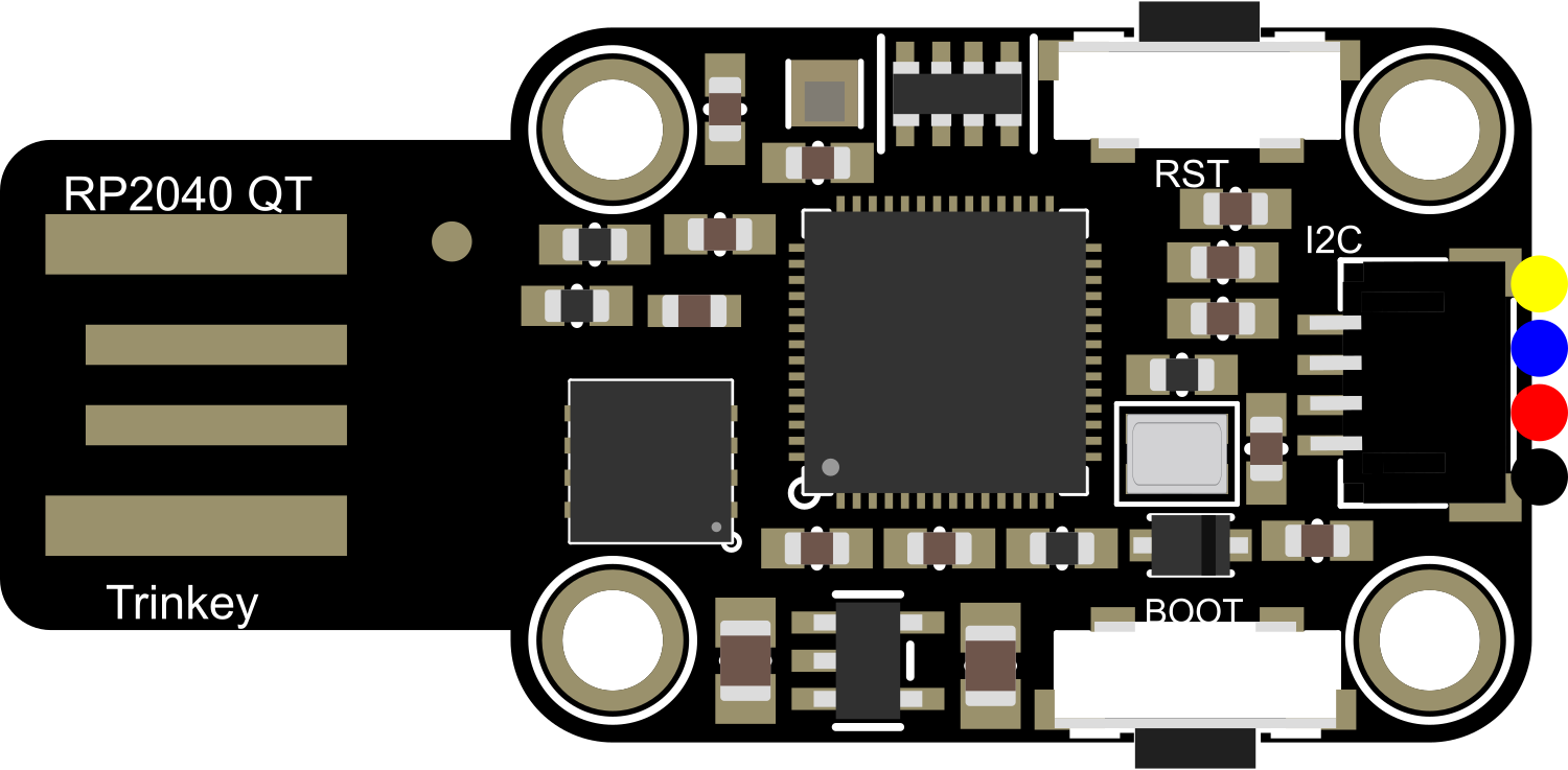
The Adafruit QT2040 Trinkey is a compact development board that harnesses the power of the Raspberry Pi RP2040 microcontroller. This board is designed for ease of use and rapid prototyping, featuring built-in sensors and buttons. It is perfect for DIY enthusiasts and professionals looking to create interactive projects or smart devices without the need for extensive wiring or peripheral components.
Explore Projects Built with Adafruit QT2040 Trinkey


Explore Projects Built with Adafruit QT2040 Trinkey
Common Applications and Use Cases
- Human-machine interface devices
- USB-based gadgets
- Quick prototyping of embedded systems
- Educational tools for learning electronics and programming
- Custom keyboard inputs or macro pads
Technical Specifications
Key Technical Details
- Microcontroller: Raspberry Pi RP2040
- Operating Voltage: 5V (USB-C)
- Digital I/O Pins: 4
- Analog Inputs: None
- Flash Memory: 8 MB
- Interfaces: USB, I2C, SPI, UART
- Built-in Sensors: Capacitive touch, NeoPixel LED
- Dimensions: 33.0mm x 17.8mm x 8.5mm
Pin Configuration and Descriptions
| Pin Number | Function | Description |
|---|---|---|
| 1 | USB VBUS | USB input voltage (5V) |
| 2 | GND | Ground |
| 3 | NEOPIXEL DATA | Data input for the onboard NeoPixel LED |
| 4 | CAP TOUCH | Capacitive touch input |
| 5 | BOOTSEL | Boot selection button, active-low |
| 6 | GND | Ground |
| 7 | 3V3_EN | 3.3V regulator enable, active-high |
| 8 | 3V3_OUT | 3.3V output from the onboard voltage regulator |
Usage Instructions
How to Use the Component in a Circuit
Powering the Board: Connect the Adafruit QT2040 Trinkey to a computer or USB power source using a USB-C cable. The board should power up and the onboard NeoPixel LED will light up.
Programming the Board: The QT2040 Trinkey can be programmed using C/C++ SDK or MicroPython. For beginners, it is recommended to start with the Thonny IDE and MicroPython for an easier setup.
Interacting with the Capacitive Touch: The capacitive touch pad can be used as an input. It can be programmed to trigger events or actions when touched.
Using the NeoPixel LED: The onboard NeoPixel LED can be controlled to display various colors and patterns. It requires a digital signal to the NEOPIXEL DATA pin.
Utilizing the BOOTSEL Button: The BOOTSEL button is used to enter the bootloader mode for firmware updates or to reprogram the flash memory.
Important Considerations and Best Practices
- Always ensure the power supply is 5V and do not exceed this voltage to prevent damage.
- When handling the board, be cautious of electrostatic discharge (ESD) and use proper grounding techniques.
- To avoid short circuits, do not place the board on conductive surfaces.
- Familiarize yourself with the RP2040 datasheet for in-depth technical information.
Troubleshooting and FAQs
Common Issues
- Board Not Recognized: Ensure the USB cable is properly connected and the computer's USB port is functioning. Try a different cable or port if necessary.
- LED Not Lighting Up: Check the NeoPixel data connection and ensure that the code is correctly uploaded to the board.
- Touch Sensitivity Issues: If the capacitive touch is not responding, ensure that the QT2040 Trinkey is not placed on a conductive surface and that the firmware is correctly configured for touch input.
Solutions and Tips for Troubleshooting
- Reset the Board: If the board is unresponsive, press the reset button or disconnect and reconnect the USB cable.
- Update Firmware: Ensure that the latest firmware is installed on the QT2040 Trinkey.
- Check Connections: Verify that all connections are secure and there are no broken or cold solder joints.
FAQs
Q: Can I use the QT2040 Trinkey with Arduino IDE? A: The QT2040 Trinkey is not natively supported by the Arduino IDE. However, you can use the Arduino-Pico core to program the RP2040 with the Arduino IDE.
Q: How do I change the color of the NeoPixel LED? A: You can change the color of the NeoPixel LED by sending digital signals to the NEOPIXEL DATA pin. This can be done using libraries available for the RP2040, such as the Adafruit NeoPixel library for MicroPython.
Q: What is the maximum current the 3V3_OUT pin can supply? A: The 3V3_OUT pin can typically supply up to 300 mA. However, it is recommended to check the latest datasheet for the exact specifications.
Example Code for Arduino UNO
#include <Adafruit_NeoPixel.h>

#define PIN        3 // NEOPIXEL DATA pin on QT2040 Trinkey
#define NUMPIXELS  1 // Number of NeoPixels

// Initialize the NeoPixel library.
Adafruit_NeoPixel pixels(NUMPIXELS, PIN, NEO_GRB + NEO_KHZ800);

void setup() {
  pixels.begin(); // Initialize the NeoPixel strip
}

void loop() {
  pixels.setPixelColor(0, pixels.Color(255, 0, 0)); // Red color
  pixels.show();   // Send the updated pixel colors to the hardware.
  delay(500);      // Pause for half a second
  pixels.clear();  // Turn off all pixels
  pixels.show();
  delay(500);
}
Note: The above example is for illustrative purposes. Since the QT2040 Trinkey is not directly compatible with Arduino UNO, you would need to adapt the code for the RP2040 environment and use appropriate libraries.