How to Use M4-ATX-HV: Examples, Pinouts, and Specs
Introduction
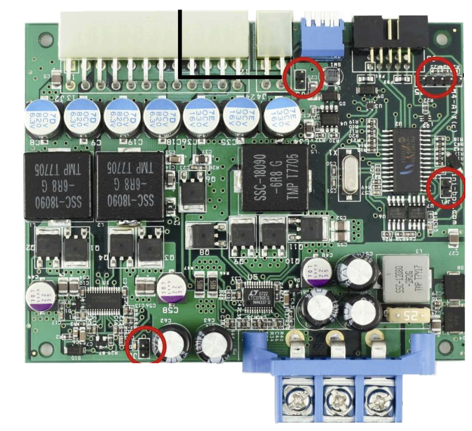
The M4-ATX-HV, manufactured by Mini-Box, is a compact, high-efficiency DC-DC power supply designed for mini-ITX and small form factor systems. It is engineered to deliver stable and reliable power output, even in demanding environments. With its wide input voltage range (6V to 34V), the M4-ATX-HV is particularly well-suited for automotive, embedded systems, and industrial applications. Its intelligent power management features make it an excellent choice for systems requiring low power consumption and high efficiency.
Explore Projects Built with M4-ATX-HV


Explore Projects Built with M4-ATX-HV
Common Applications
- Automotive PCs and infotainment systems
- Embedded computing platforms
- Industrial control systems
- Mini-ITX and small form factor PCs
- Battery-powered devices and systems
Technical Specifications
Key Technical Details
| Parameter | Value |
|---|---|
| Input Voltage Range | 6V to 34V DC |
| Output Voltage Rails | +12V, +5V, +3.3V, -12V |
| Maximum Power Output | 250W |
| Efficiency | Up to 95% |
| Operating Temperature Range | -40°C to +85°C |
| Dimensions | 160mm x 45mm x 25mm |
| Protection Features | Over-voltage, under-voltage, over-current, short-circuit |
Pin Configuration and Descriptions
The M4-ATX-HV features a standard ATX power connector and additional input/output pins for advanced functionality.
ATX Power Connector Pinout
| Pin Number | Signal Name | Voltage Level | Description |
|---|---|---|---|
| 1 | +3.3V | +3.3V | Main 3.3V power rail |
| 2 | +5V | +5V | Main 5V power rail |
| 3 | +12V | +12V | Main 12V power rail |
| 4 | -12V | -12V | Negative 12V power rail |
| 5 | GND | 0V | Ground |
| 6 | PS_ON | Logic Signal | Power supply on/off control |
| 7 | 5VSB | +5V Standby | Standby power for low-power mode |
Input Power Connector
| Pin Number | Signal Name | Voltage Level | Description |
|---|---|---|---|
| 1 | VIN+ | 6V to 34V | Positive input voltage |
| 2 | VIN- | 0V | Ground/negative input voltage |
Usage Instructions
How to Use the M4-ATX-HV in a Circuit
- Input Power Connection: Connect the input power source (e.g., car battery or DC adapter) to the VIN+ and VIN- terminals. Ensure the input voltage is within the 6V to 34V range.
- ATX Power Connection: Connect the ATX power connector to the motherboard or device requiring power.
- Power On/Off Control: Use the PS_ON pin to control the power supply. Pulling this pin low will turn the power supply on, while leaving it high will turn it off.
- Standby Power: The 5VSB pin provides standby power for devices that require low-power operation when the main power is off.
Important Considerations
- Input Voltage Range: Ensure the input voltage remains within the specified range to avoid damage to the power supply.
- Cooling: While the M4-ATX-HV is highly efficient, ensure adequate ventilation to prevent overheating in high-power applications.
- Load Balancing: Distribute the load evenly across the output rails to maintain stable operation.
- Fuse Protection: Use an appropriate fuse on the input power line to protect against over-current conditions.
Example: Using the M4-ATX-HV with an Arduino UNO
The M4-ATX-HV can be used to power an Arduino UNO and other peripherals in an embedded system. Below is an example of how to connect the power supply:
- Connect the +5V rail from the ATX connector to the Arduino UNO's 5V pin.
- Connect the GND rail from the ATX connector to the Arduino UNO's GND pin.
- Use the 5VSB pin to power low-power peripherals when the main system is off.
Sample Arduino Code for Power Monitoring
The M4-ATX-HV can be paired with a voltage sensor to monitor the input voltage. Below is an example Arduino sketch:
// Arduino sketch to monitor input voltage of the M4-ATX-HV
const int voltagePin = A0; // Analog pin connected to voltage sensor
const float voltageDividerRatio = 11.0; // Adjust based on your voltage divider

void setup() {
  Serial.begin(9600); // Initialize serial communication
  pinMode(voltagePin, INPUT); // Set voltage pin as input
}

void loop() {
  int sensorValue = analogRead(voltagePin); // Read analog value
  // Convert the analog value to voltage
  float inputVoltage = (sensorValue * 5.0 / 1023.0) * voltageDividerRatio;

  // Print the input voltage to the Serial Monitor
  Serial.print("Input Voltage: ");
  Serial.print(inputVoltage);
  Serial.println(" V");

  delay(1000); // Wait for 1 second before the next reading
}
Troubleshooting and FAQs
Common Issues and Solutions
Power Supply Does Not Turn On
- Cause: PS_ON pin is not properly connected.
- Solution: Ensure the PS_ON pin is pulled low to enable the power supply.
Overheating
- Cause: Insufficient ventilation or excessive load.
- Solution: Improve airflow around the power supply and ensure the load does not exceed 250W.
Output Voltage Instability
- Cause: Input voltage is outside the specified range.
- Solution: Verify that the input voltage is between 6V and 34V.
No Standby Power
- Cause: 5VSB pin is not connected or overloaded.
- Solution: Check the connection to the 5VSB pin and ensure the standby load is within limits.
FAQs
Q: Can the M4-ATX-HV be used in a 24V automotive system?
A: Yes, the M4-ATX-HV supports input voltages up to 34V, making it compatible with 24V systems.
Q: Does the M4-ATX-HV require an external cooling fan?
A: In most cases, passive cooling is sufficient. However, for high-power applications, additional cooling may be necessary.
Q: Can I use the M4-ATX-HV to power multiple devices?
A: Yes, as long as the total power consumption does not exceed 250W and the load is distributed across the output rails.
Q: Is the M4-ATX-HV protected against short circuits?
A: Yes, the power supply includes short-circuit protection to safeguard connected devices.
This concludes the documentation for the Mini-Box M4-ATX-HV. For further assistance, refer to the manufacturer's user manual or contact Mini-Box support.