How to Use Drv8833: Examples, Pinouts, and Specs
Introduction
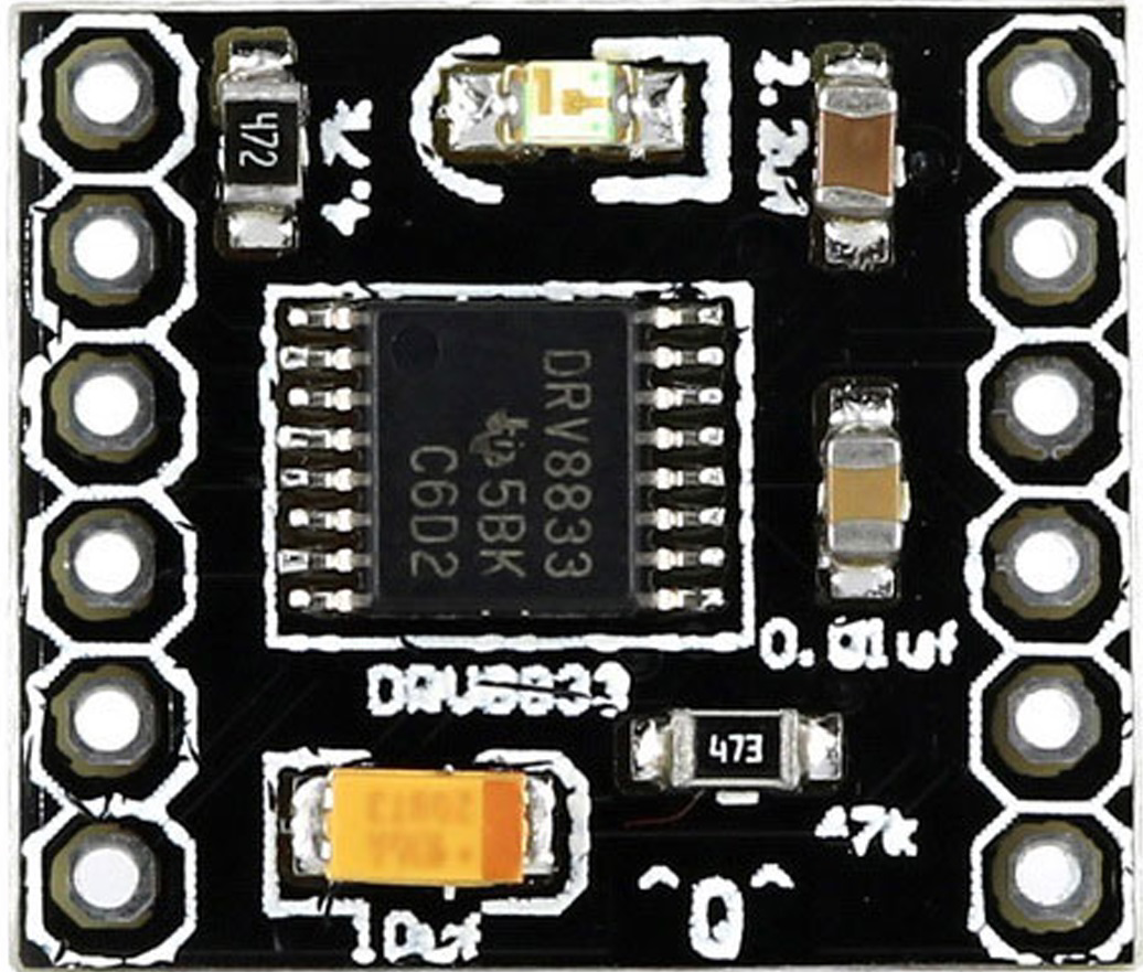
The DRV8833 is a versatile dual H-bridge motor driver integrated circuit (IC) designed to drive two DC motors or one bipolar stepper motor. It is widely used in robotics, mechatronics, and other applications requiring precise motor control. The DRV8833 allows for control of the direction and speed of motors, making it an essential component for projects that require independent motor manipulation.
Explore Projects Built with Drv8833
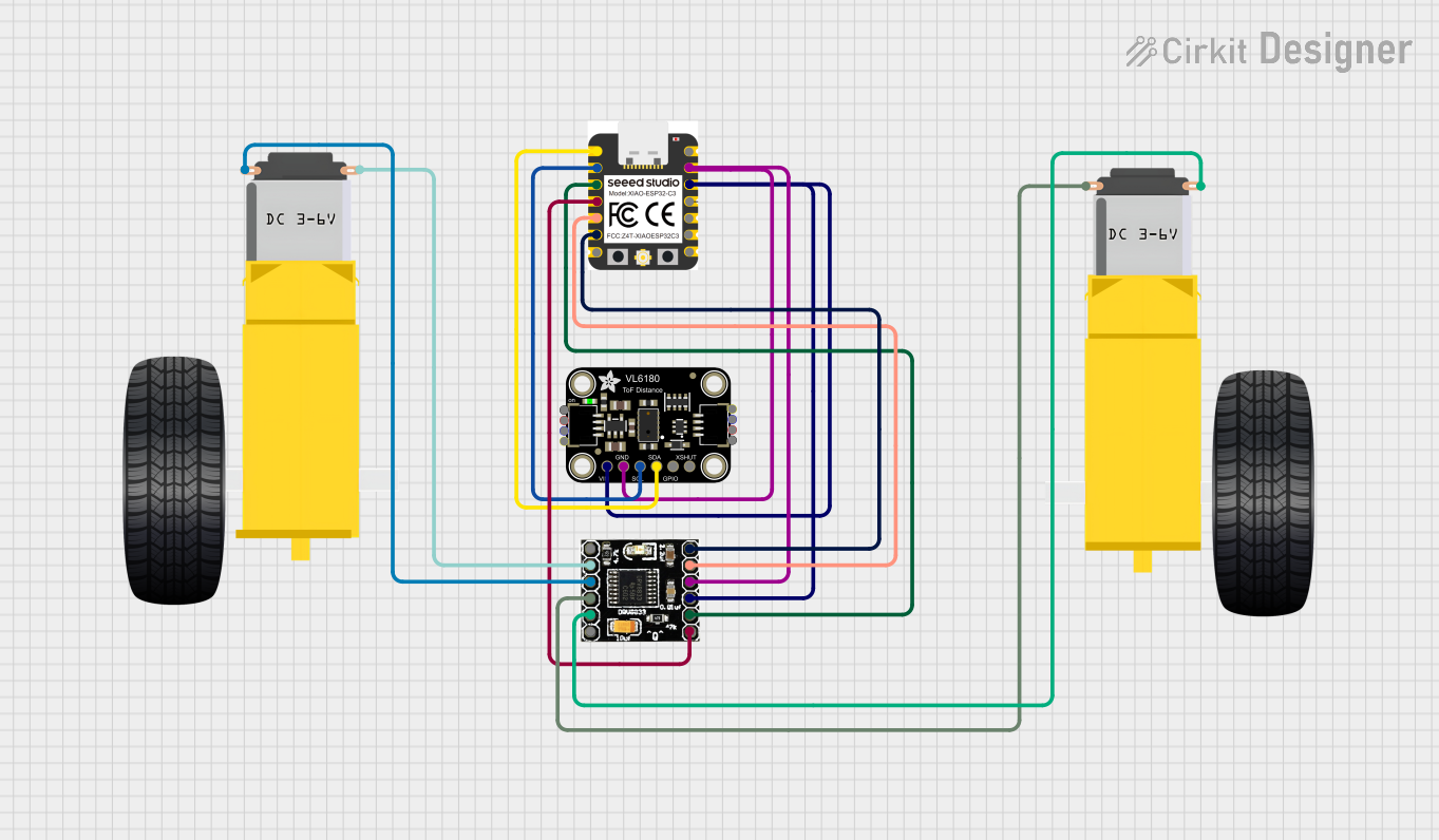
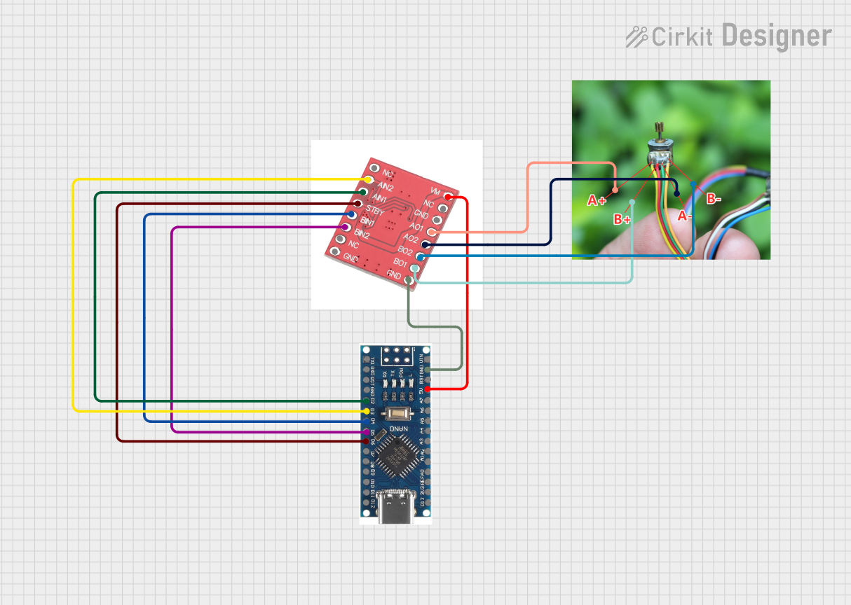

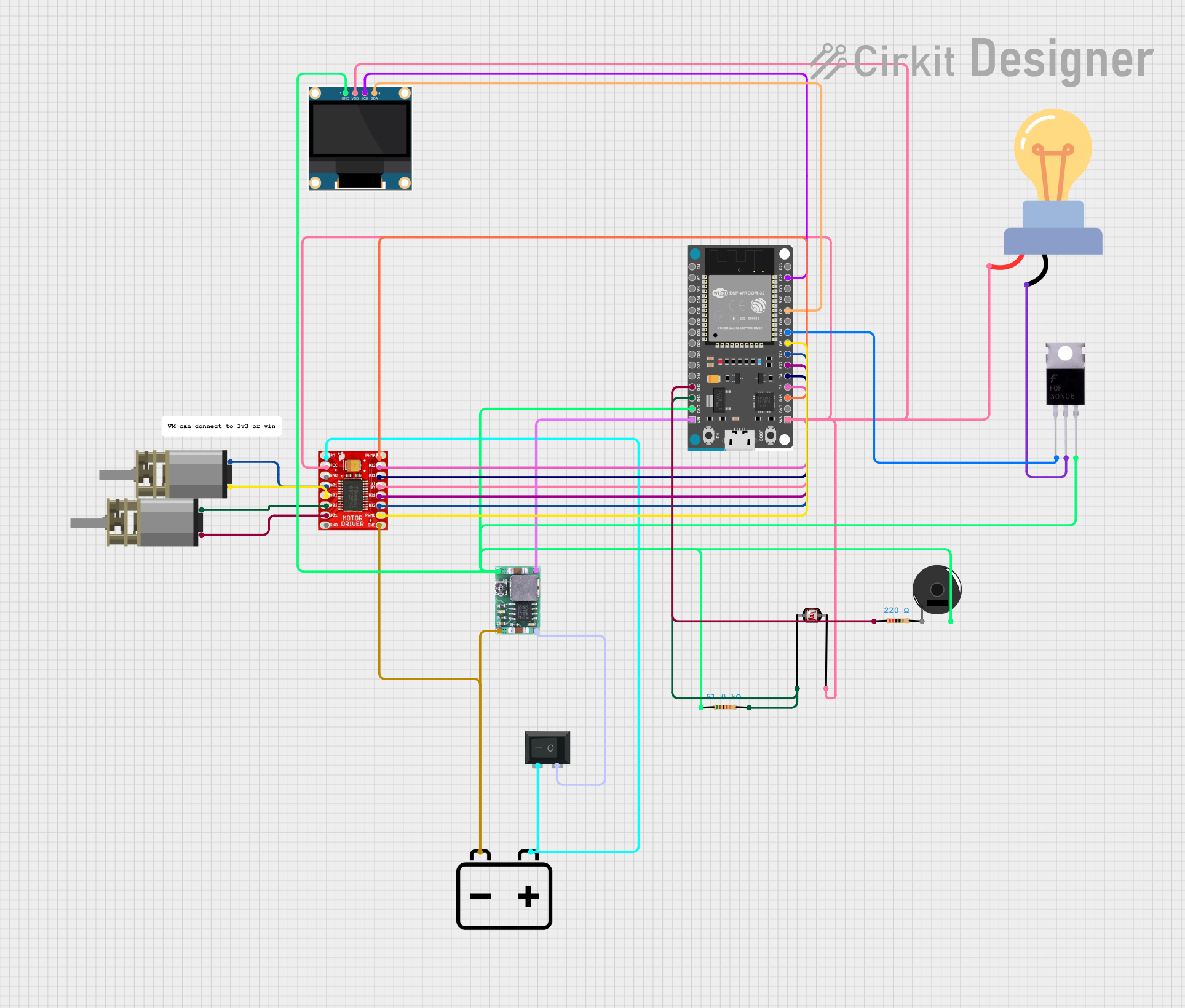
Explore Projects Built with Drv8833
Common Applications and Use Cases
- Robotics: driving wheels or actuator motors
- Mechatronics: controlling mechanical systems with electronic components
- Hobbyist projects: RC cars, drones, and other DIY electronics
- Educational purposes: teaching motor control principles
Technical Specifications
Key Technical Details
- Motor supply voltage (VM): 2.7V to 10.8V
- Output current: 1.5A per channel (peak) or 1.2A (RMS) continuous
- Low-power sleep mode
- Built-in thermal shutdown and under-voltage lockout
- Individual channel control via parallel interface
Pin Configuration and Descriptions
| Pin Number | Pin Name | Description |
|---|---|---|
| 1 | xIN1 | Input control for motor 1, channel A |
| 2 | xIN2 | Input control for motor 1, channel B |
| 3 | xOUT1 | Output for motor 1, channel A |
| 4 | xOUT2 | Output for motor 1, channel B |
| 5 | VMM | Motor power supply |
| 6 | GND | Ground |
| 7 | yIN1 | Input control for motor 2, channel A |
| 8 | yIN2 | Input control for motor 2, channel B |
| 9 | yOUT1 | Output for motor 2, channel A |
| 10 | yOUT2 | Output for motor 2, channel B |
| 11 | VM | Logic power supply |
| 12 | nFAULT | Fault indication output (active low) |
| 13 | nSLEEP | Sleep mode enable (active low) |
Usage Instructions
How to Use the DRV8833 in a Circuit
- Connect the motor power supply (VM) to pin 5 and ground (GND) to pin 6.
- Apply the logic power supply (VCC) to pin 11.
- Connect the motors to the xOUT1/xOUT2 and yOUT1/yOUT2 pairs.
- Control the motor direction and speed by applying logic signals to xIN1/xIN2 and yIN1/yIN2.
- Use the nSLEEP pin to put the IC into low-power mode when not in use.
- Monitor the nFAULT pin for fault conditions.
Important Considerations and Best Practices
- Ensure the power supply does not exceed the maximum voltage rating.
- Provide adequate heat sinking if operating near the peak current ratings.
- Use flyback diodes if driving inductive loads to protect against voltage spikes.
- Avoid shorting the output pins as this can damage the IC.
- Implement proper decoupling techniques to minimize noise and voltage fluctuations.
Troubleshooting and FAQs
Common Issues
- Motor not running: Check power supplies, input signals, and connections.
- Overheating: Ensure proper heat sinking and current limits are not exceeded.
- Unexpected behavior: Verify that the logic signals are within the specified voltage range and timings.
Solutions and Tips for Troubleshooting
- If the motor does not run, verify that the power supply is correctly connected and within the specified voltage range.
- Check for solder bridges or shorts that could affect the IC's operation.
- Use a multimeter to check the continuity of the motor windings.
- Ensure that the logic inputs are being driven correctly; a microcontroller or similar device can be used for this purpose.
FAQs
Q: Can the DRV8833 drive stepper motors? A: Yes, the DRV8833 can drive one bipolar stepper motor by controlling the current in each coil.
Q: What is the function of the nFAULT pin? A: The nFAULT pin is an open-drain output that goes low when a fault condition occurs, such as overcurrent or thermal shutdown.
Q: How can I control the speed of the motors? A: Speed control can be achieved by using pulse-width modulation (PWM) signals on the input pins.
Example Code for Arduino UNO
// Example code to control a DC motor with the DRV8833 and Arduino UNO

const int in1Pin = 2; // xIN1 connected to digital pin 2
const int in2Pin = 3; // xIN2 connected to digital pin 3

void setup() {
  pinMode(in1Pin, OUTPUT);
  pinMode(in2Pin, OUTPUT);
}

void loop() {
  // Set motor direction to forward
  digitalWrite(in1Pin, HIGH);
  digitalWrite(in2Pin, LOW);

  // Run the motor for 2 seconds
  delay(2000);

  // Set motor direction to reverse
  digitalWrite(in1Pin, LOW);
  digitalWrite(in2Pin, HIGH);

  // Run the motor for 2 seconds
  delay(2000);

  // Stop the motor
  digitalWrite(in1Pin, LOW);
  digitalWrite(in2Pin, LOW);

  // Wait for 2 seconds
  delay(2000);
}
This example demonstrates basic forward and reverse control of a DC motor using the DRV8833. For speed control, you would replace the digitalWrite functions with analogWrite to apply PWM signals to the input pins.