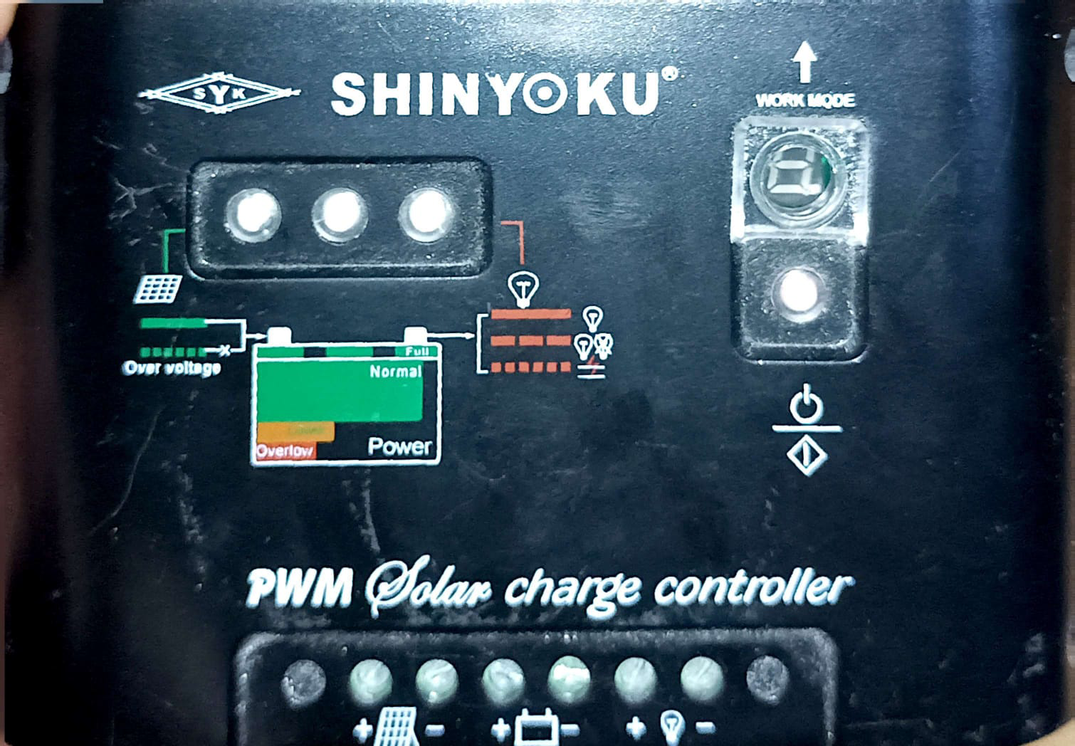
A Switching Converter Controller (SCC) is a device designed to regulate the output voltage of a power supply by controlling the switching of power transistors. This enables efficient power conversion and management, making it an essential component in modern electronic systems. SCCs are widely used in applications requiring high efficiency, compact size, and precise voltage regulation.
Explore Projects Built with SCC
Use Cirkit Designer to design, explore, and prototype these projects online. Some projects support real-time simulation. Click "Open Project" to start designing instantly!
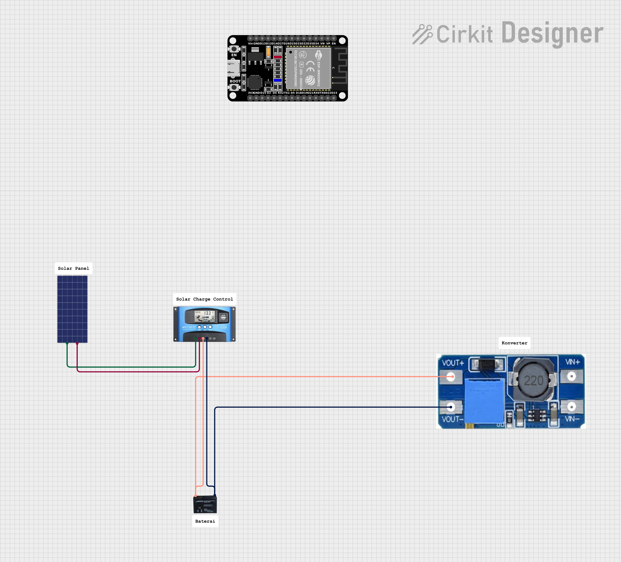
This circuit is a solar-powered battery charging system with an MPPT (Maximum Power Point Tracking) charge controller. The solar panel provides power to the MPPT SCC, which optimizes the charging of a 12V battery. A step-up boost converter is used to regulate the output voltage from the battery.
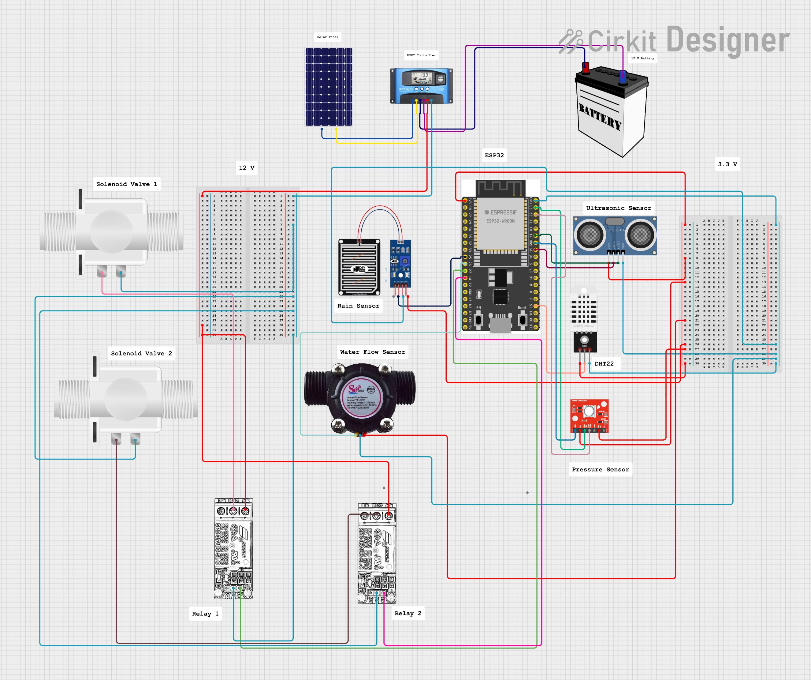
This is a solar-powered environmental monitoring and water flow control system. It uses an ESP32 microcontroller to process data from multiple sensors and manage water flow through solenoid valves, with power regulation handled by an MPPT Solar Charge Controller connected to a solar panel and a 12V battery.
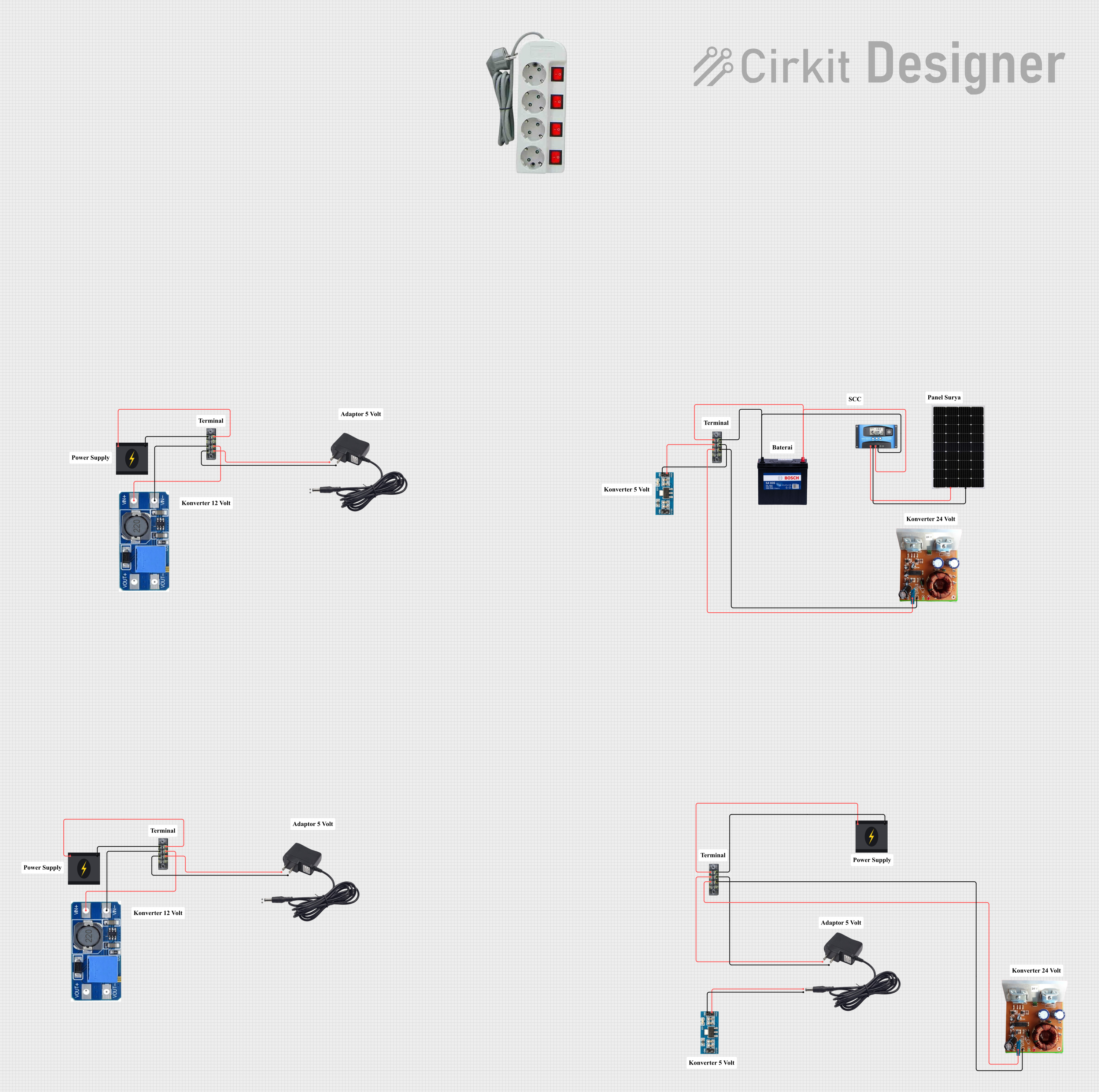
This circuit is a solar power management system that includes a solar panel, an MPPT solar charge controller, a 12V 200Ah battery, and various voltage converters. The system is designed to harness solar energy, store it in a battery, and provide regulated power outputs at different voltages for various loads.
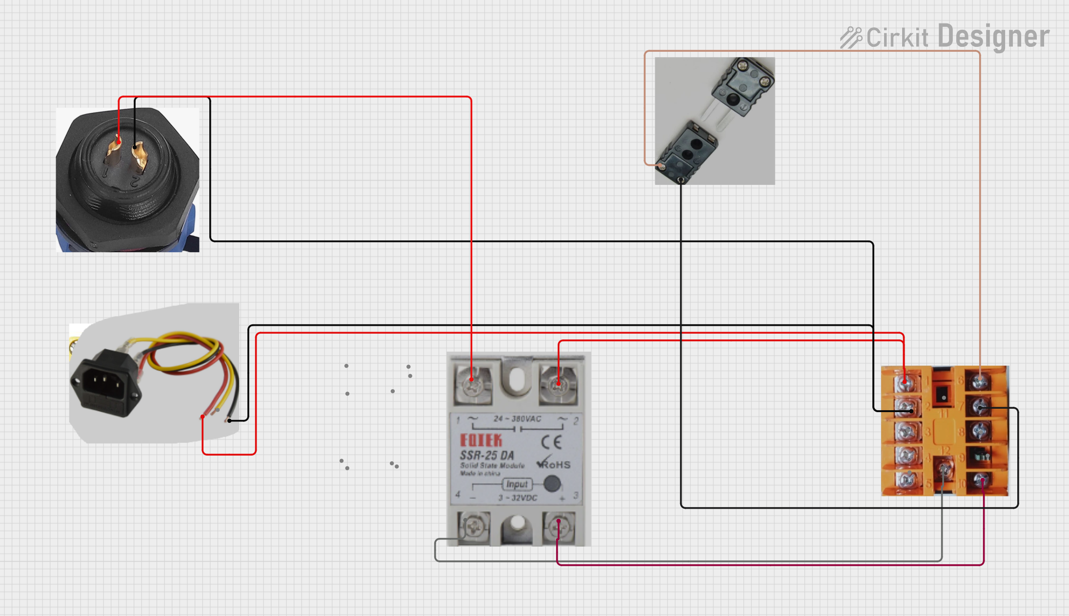
This circuit is a temperature control system that uses a thermocouple to measure temperature and a PID controller to regulate it. The PID controller drives a solid-state relay (SSR) to control an external load, with power supplied through an AC inlet socket.
The following table describes the typical pinout of an SCC:
Pin Number
Pin Name
Description
1
VIN
Input voltage pin. Connects to the input power supply.
2
GND
Ground pin. Connects to the system ground.
3
VOUT
Output voltage pin. Provides the regulated output voltage.
4
FB (Feedback)
Feedback pin. Used to monitor and regulate the output voltage.
5
EN (Enable)
Enable pin. Used to turn the SCC on or off.
6
COMP
Compensation pin. Connects to external components for stability and performance.
7
SW (Switch)
Switch pin. Connects to the power transistor for switching control.
8
RT/CLK
Timing resistor or clock input pin. Sets the switching frequency.
Usage Instructions
How to Use the SCC in a Circuit
Input and Output Connections:
Connect the input voltage source to the VIN pin and ground to the GND pin.
Connect the load to the VOUT pin.
Feedback Configuration:
Use a resistor divider network to connect the FB pin to the output voltage. This ensures proper voltage regulation.
Switching Frequency:
Connect a resistor to the RT/CLK pin to set the desired switching frequency. Refer to the SCC datasheet for recommended resistor values.
Enable Pin:
Use the EN pin to enable or disable the SCC. Pull it high to enable the controller or low to disable it.
Compensation Network:
Connect external components (e.g., capacitors and resistors) to the COMP pin to stabilize the control loop.
Thermal Management:
Ensure proper heat dissipation by using a heatsink or placing the SCC on a PCB with adequate thermal vias.
Important Considerations and Best Practices
Input Capacitor: Place a low-ESR capacitor close to the VIN pin to reduce input voltage ripple.
Output Capacitor: Use a capacitor with sufficient capacitance and low ESR to minimize output voltage ripple.
Inductor Selection: Choose an inductor with the appropriate current rating and inductance value for your application.
PCB Layout: Minimize the length of high-current paths and place decoupling capacitors close to the SCC pins.
Example: Using SCC with Arduino UNO
Below is an example of how to use an SCC to power an Arduino UNO with a regulated 5V output:
Circuit Connections
Connect a 12V DC power supply to the VIN pin of the SCC.
Set the output voltage to 5V using a resistor divider on the FB pin.
Connect the VOUT pin of the SCC to the 5V pin of the Arduino UNO.
Connect the GND pin of the SCC to the GND pin of the Arduino UNO.
Arduino Code Example
// Example code to monitor the SCC output voltage using Arduino UNO
// Connect the SCC output to an analog input pin (e.g., A0)

const int voltagePin = A0; // Analog pin connected to SCC output
float voltage = 0.0;

void setup() {
  Serial.begin(9600); // Initialize serial communication
}

void loop() {
  int sensorValue = analogRead(voltagePin); // Read the analog value
  voltage = sensorValue * (5.0 / 1023.0);   // Convert to voltage (assuming 5V ADC ref)

  // Print the voltage to the Serial Monitor
  Serial.print("SCC Output Voltage: ");
  Serial.print(voltage);
  Serial.println(" V");

  delay(1000); // Wait for 1 second
}
Troubleshooting and FAQs
Common Issues and Solutions
No Output Voltage:
Ensure the EN pin is pulled high to enable the SCC.
Check the input voltage and ensure it is within the specified range.
Verify the feedback resistor network is correctly configured.
Excessive Heat:
Check for proper heat dissipation and ensure the SCC is not overloaded.
Verify the inductor and capacitors are rated for the application.
Output Voltage Instability:
Ensure the compensation network is correctly designed.
Check for proper PCB layout and minimize noise on the feedback pin.
High Output Ripple:
Use low-ESR capacitors on the output.
Verify the inductor value and switching frequency are appropriate.
FAQs
Q: Can the SCC be used for battery charging?
A: Yes, SCCs can be configured for battery charging applications by adjusting the output voltage and current limits.
Q: How do I calculate the feedback resistor values?
A: Use the formula: VOUT = VREF * (1 + R1/R2), where VREF is the reference voltage of the SCC, and R1 and R2 are the feedback resistors.
Q: What happens if the input voltage drops below the specified range?
A: The SCC may stop regulating the output voltage, leading to instability or shutdown. Ensure the input voltage remains within the recommended range.
This concludes the documentation for the Switching Converter Controller (SCC).

 Open Project in Cirkit Designer