Cirkit Designer Logo
Cirkit Designer
Your all-in-one circuit design IDE
Home / 
Component Documentation

How to Use Microzone MC7RB: Examples, Pinouts, and Specs

Image of Microzone MC7RB
Cirkit Designer LogoDesign with Microzone MC7RB in Cirkit Designer

Introduction

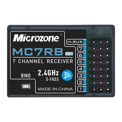
The Microzone MC7RB is a versatile and compact microcontroller that is widely used in a variety of electronic projects and applications. Its small form factor and robust feature set make it suitable for hobbyists and professionals alike. Common applications include DIY electronics, robotics, sensor integration, and automation systems.

Explore Projects Built with Microzone MC7RB

Use Cirkit Designer to design, explore, and prototype these projects online. Some projects support real-time simulation. Click "Open Project" to start designing instantly!
Arduino Mega 2560 Brushless Motor Controller with ESC and Microzone MC7RB
Image of aaa: A project utilizing Microzone MC7RB in a practical application
This circuit uses an Arduino Mega 2560 to control a brushless motor via an Electronic Speed Controller (ESC). The Microzone MC7RB is also connected to the Arduino for additional PWM control, and the ESC is responsible for driving the motor based on signals from the Arduino.
Cirkit Designer LogoOpen Project in Cirkit Designer
WiFi LoRa Environmental Monitoring System with INMP441 Mic and Multiple Sensors
Image of ba_sensing: A project utilizing Microzone MC7RB in a practical application
This circuit is a solar-powered environmental monitoring system that uses a WiFi LoRa 32V3 microcontroller to collect data from various sensors, including a microphone, UV light sensor, air quality sensor, and temperature/humidity/pressure sensor. The collected data is processed and transmitted via LoRa communication, making it suitable for remote environmental data logging and monitoring applications.
Cirkit Designer LogoOpen Project in Cirkit Designer
Battery-Powered Line Following Robot with IR Sensors and Cytron URC10 Motor Controller
Image of URC10 SUMO AUTO: A project utilizing Microzone MC7RB in a practical application
This circuit is a robotic control system that uses multiple IR sensors for line detection and obstacle avoidance, powered by a 3S LiPo battery. The Cytron URC10 motor driver, controlled by a microcontroller, drives two GM25 DC motors based on input from the sensors and a rocker switch, with a 7-segment panel voltmeter displaying the battery voltage.
Cirkit Designer LogoOpen Project in Cirkit Designer
ESP8266 NodeMCU with LoRa and RS-485 Communication and Ethernet Connectivity
Image of Wiring Diagram LoRa: A project utilizing Microzone MC7RB in a practical application
This circuit serves as a multi-protocol communication hub featuring two ESP8266 NodeMCUs for processing, each connected to a LoRa Ra-02 SX1278 for long-range wireless communication. One NodeMCU is also connected to an RS-485 module for serial communication and a W5500 Ethernet module for network connectivity, with MB102 modules supplying power.
Cirkit Designer LogoOpen Project in Cirkit Designer

Explore Projects Built with Microzone MC7RB

Use Cirkit Designer to design, explore, and prototype these projects online. Some projects support real-time simulation. Click "Open Project" to start designing instantly!
Image of aaa: A project utilizing Microzone MC7RB in a practical application
Arduino Mega 2560 Brushless Motor Controller with ESC and Microzone MC7RB
This circuit uses an Arduino Mega 2560 to control a brushless motor via an Electronic Speed Controller (ESC). The Microzone MC7RB is also connected to the Arduino for additional PWM control, and the ESC is responsible for driving the motor based on signals from the Arduino.
Cirkit Designer LogoOpen Project in Cirkit Designer
Image of ba_sensing: A project utilizing Microzone MC7RB in a practical application
WiFi LoRa Environmental Monitoring System with INMP441 Mic and Multiple Sensors
This circuit is a solar-powered environmental monitoring system that uses a WiFi LoRa 32V3 microcontroller to collect data from various sensors, including a microphone, UV light sensor, air quality sensor, and temperature/humidity/pressure sensor. The collected data is processed and transmitted via LoRa communication, making it suitable for remote environmental data logging and monitoring applications.
Cirkit Designer LogoOpen Project in Cirkit Designer
Image of URC10 SUMO AUTO: A project utilizing Microzone MC7RB in a practical application
Battery-Powered Line Following Robot with IR Sensors and Cytron URC10 Motor Controller
This circuit is a robotic control system that uses multiple IR sensors for line detection and obstacle avoidance, powered by a 3S LiPo battery. The Cytron URC10 motor driver, controlled by a microcontroller, drives two GM25 DC motors based on input from the sensors and a rocker switch, with a 7-segment panel voltmeter displaying the battery voltage.
Cirkit Designer LogoOpen Project in Cirkit Designer
Image of Wiring Diagram LoRa: A project utilizing Microzone MC7RB in a practical application
ESP8266 NodeMCU with LoRa and RS-485 Communication and Ethernet Connectivity
This circuit serves as a multi-protocol communication hub featuring two ESP8266 NodeMCUs for processing, each connected to a LoRa Ra-02 SX1278 for long-range wireless communication. One NodeMCU is also connected to an RS-485 module for serial communication and a W5500 Ethernet module for network connectivity, with MB102 modules supplying power.
Cirkit Designer LogoOpen Project in Cirkit Designer

Technical Specifications

General Features

  • Microcontroller Core: 8-bit
  • Operating Voltage: 3.3V - 5V
  • Digital I/O Pins: 14 (of which 6 provide PWM output)
  • Analog Input Pins: 6
  • Flash Memory: 32 KB (of which 2 KB used by bootloader)
  • SRAM: 2 KB
  • EEPROM: 1 KB
  • Clock Speed: 16 MHz

Pin Configuration and Descriptions

Pin Number Function Description
1 VCC Power supply input (3.3V - 5V)
2 GND Ground
3-5 Digital I/O General-purpose digital input/output pins
6-11 PWM/Digital I/O Digital input/output with PWM capability
12-17 Analog Input Analog input pins (A0-A5)
18 RESET Resets the microcontroller

Usage Instructions

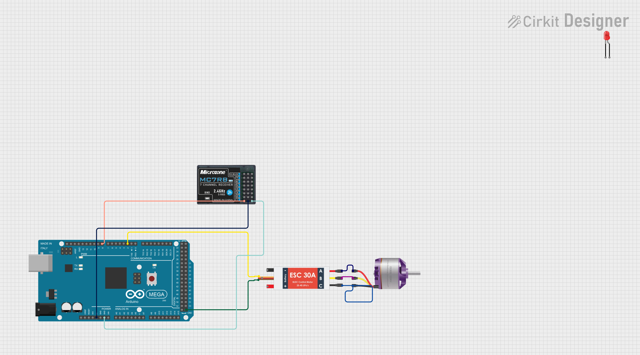
Integrating with a Circuit

  1. Powering the MC7RB: Connect the VCC pin to a 3.3V - 5V power supply and the GND pin to the common ground in your circuit.
  2. Programming the MC7RB: Use a compatible programmer to upload your code to the microcontroller via the ICSP header.
  3. Using Digital I/O: Configure the pins as input or output according to your needs using the pinMode() function in your code.
  4. Using PWM: To control devices like motors or LEDs with variable intensity, use the PWM-capable pins with the analogWrite() function.
  5. Reading Analog Inputs: Connect sensors to the analog pins and use the analogRead() function to get sensor readings.

Best Practices

  • Always ensure that the power supply voltage is within the specified range to prevent damage.
  • Use current-limiting resistors with LEDs to prevent overcurrent.
  • When using PWM, ensure that the connected device can handle the frequency and duty cycle.
  • Avoid exposing the pins to voltages higher than VCC or lower than GND to prevent damage.

Troubleshooting and FAQs

Common Issues

  • MC7RB not responding: Ensure that the power supply is connected correctly and the programmer is functioning.
  • Incorrect readings from pins: Verify that the pin configurations in your code match the physical connections.
  • Unexpected behavior: Double-check your code for logical errors and ensure that all connections are secure.

FAQs

Q: Can I use the MC7RB with a 3.3V system? A: Yes, the MC7RB can operate at 3.3V, but ensure that all connected components are compatible with this voltage.

Q: How do I reset the MC7RB? A: You can reset the MC7RB by momentarily connecting the RESET pin to GND.

Q: What is the maximum current the I/O pins can source/sink? A: Each I/O pin can source or sink a maximum of 40 mA, but the total current for all pins should not exceed 200 mA.

Example Code for Arduino UNO

// Example code for blinking an LED connected to pin 13 of the Microzone MC7RB

void setup() {
  pinMode(13, OUTPUT); // Set pin 13 as an output
}

void loop() {
  digitalWrite(13, HIGH); // Turn the LED on
  delay(1000);            // Wait for a second
  digitalWrite(13, LOW);  // Turn the LED off
  delay(1000);            // Wait for a second
}

Note: The example code provided is compatible with the Arduino UNO environment, as the MC7RB shares similar characteristics. Make sure to select the correct board and port in your Arduino IDE before uploading the code.

For further assistance or more complex applications, consider consulting the datasheet or reaching out to the community forums for support.