How to Use M5Stack Color Sensor: Examples, Pinouts, and Specs
Introduction
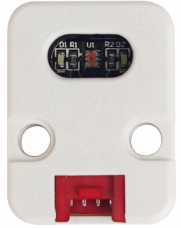
The M5Stack Color Sensor (Manufacturer Part ID: U009) is a compact and versatile sensor module designed to detect and identify colors in the environment. It features RGB color detection capabilities, making it ideal for applications requiring color recognition, sorting, or classification. The module is easy to integrate with microcontrollers, including Arduino and ESP32-based systems, thanks to its straightforward interfacing options.
Explore Projects Built with M5Stack Color Sensor

Explore Projects Built with M5Stack Color Sensor
Common Applications and Use Cases
- Color Sorting Systems: Used in robotics and automation for sorting objects by color.
- Environmental Monitoring: Detecting and analyzing color changes in the environment.
- Educational Projects: Ideal for STEM learning and prototyping.
- Consumer Electronics: Used in devices requiring color-based input or feedback.
Technical Specifications
The M5Stack Color Sensor is built for reliability and ease of use. Below are its key technical details:
Key Technical Details
- Manufacturer: M5Stack
- Part ID: U009
- Operating Voltage: 3.3V to 5V
- Communication Protocol: I2C
- I2C Address: 0x29 (default)
- Detection Range: RGB color spectrum
- Dimensions: 24mm x 24mm x 5mm
- Operating Temperature: -20°C to 85°C
Pin Configuration and Descriptions
The M5Stack Color Sensor has a 4-pin interface for easy connection. Below is the pinout:
| Pin | Name | Description |
|---|---|---|
| 1 | VIN | Power input (3.3V to 5V) |
| 2 | GND | Ground |
| 3 | SDA | I2C data line |
| 4 | SCL | I2C clock line |
Usage Instructions
The M5Stack Color Sensor is straightforward to use in a circuit. Follow the steps below to integrate it into your project:
Connecting the Sensor
- Power Supply: Connect the VIN pin to a 3.3V or 5V power source and the GND pin to ground.
- I2C Communication: Connect the SDA pin to the SDA pin of your microcontroller and the SCL pin to the SCL pin of your microcontroller.
- Pull-Up Resistors: Ensure that the I2C lines (SDA and SCL) have pull-up resistors (typically 4.7kΩ) if not already provided by your microcontroller.
Example Code for Arduino UNO
Below is an example Arduino sketch to read RGB values from the M5Stack Color Sensor:
#include <Wire.h>

// I2C address of the M5Stack Color Sensor
#define COLOR_SENSOR_ADDR 0x29

void setup() {
  Wire.begin(); // Initialize I2C communication
  Serial.begin(9600); // Start serial communication for debugging

  // Initialize the sensor
  if (!initializeColorSensor()) {
    Serial.println("Failed to initialize color sensor!");
    while (1); // Halt execution if initialization fails
  }
  Serial.println("Color sensor initialized successfully.");
}

void loop() {
  int red, green, blue;

  // Read RGB values from the sensor
  if (readColor(&red, &green, &blue)) {
    Serial.print("Red: ");
    Serial.print(red);
    Serial.print(", Green: ");
    Serial.print(green);
    Serial.print(", Blue: ");
    Serial.println(blue);
  } else {
    Serial.println("Failed to read color data.");
  }

  delay(500); // Wait for 500ms before the next reading
}

bool initializeColorSensor() {
  Wire.beginTransmission(COLOR_SENSOR_ADDR);
  // Send initialization commands if required by the sensor
  // (Refer to the sensor's datasheet for specific commands)
  return (Wire.endTransmission() == 0);
}

bool readColor(int *red, int *green, int *blue) {
  Wire.beginTransmission(COLOR_SENSOR_ADDR);
  // Request color data from the sensor
  // (Refer to the sensor's datasheet for specific register addresses)
  if (Wire.endTransmission() != 0) {
    return false; // Communication error
  }

  Wire.requestFrom(COLOR_SENSOR_ADDR, 6); // Request 6 bytes (R, G, B data)
  if (Wire.available() == 6) {
    *red = Wire.read() << 8 | Wire.read();   // Combine high and low bytes
    *green = Wire.read() << 8 | Wire.read(); // Combine high and low bytes
    *blue = Wire.read() << 8 | Wire.read();  // Combine high and low bytes
    return true;
  }
  return false; // Data not available
}
Important Considerations and Best Practices
- Power Supply: Ensure the sensor is powered within its operating voltage range (3.3V to 5V).
- I2C Address Conflicts: If multiple I2C devices are connected, ensure they have unique addresses.
- Ambient Light: Avoid direct exposure to intense light sources, as this may affect color detection accuracy.
- Calibration: For precise applications, calibrate the sensor to account for environmental factors.
Troubleshooting and FAQs
Common Issues and Solutions
Sensor Not Detected on I2C Bus:
- Ensure the SDA and SCL lines are correctly connected.
- Check for proper pull-up resistors on the I2C lines.
- Verify the I2C address (default: 0x29) matches the code.
Incorrect Color Readings:
- Ensure the sensor is not exposed to direct sunlight or strong artificial light.
- Calibrate the sensor for your specific application.
No Data Output:
- Verify the power supply voltage is within the specified range.
- Check all connections for loose or incorrect wiring.
FAQs
Q: Can the sensor detect colors in low light conditions?
A: Yes, the sensor can detect colors in low light, but accuracy may decrease. Consider using an external light source for consistent results.
Q: Is the sensor compatible with Raspberry Pi?
A: Yes, the sensor can be used with Raspberry Pi via the I2C interface. Ensure proper configuration of the I2C pins.
Q: How do I change the I2C address of the sensor?
A: Refer to the sensor's datasheet for instructions on modifying the I2C address, if supported.
This concludes the documentation for the M5Stack Color Sensor. For further assistance, consult the official M5Stack documentation or community forums.