How to Use Vout: Examples, Pinouts, and Specs

Introduction
Vout, or Output Voltage, is a fundamental concept in electronics, referring to the voltage level delivered from a circuit to a load or another part of the circuit. It is a critical parameter in power supply units, voltage regulators, amplifiers, and many other electronic circuits. Understanding and controlling Vout is essential for ensuring the proper operation of electronic devices, as it affects the performance and reliability of the entire system.
Explore Projects Built with Vout

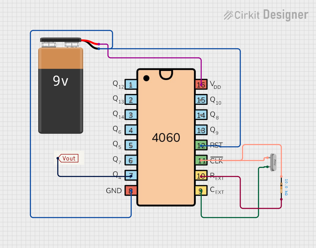
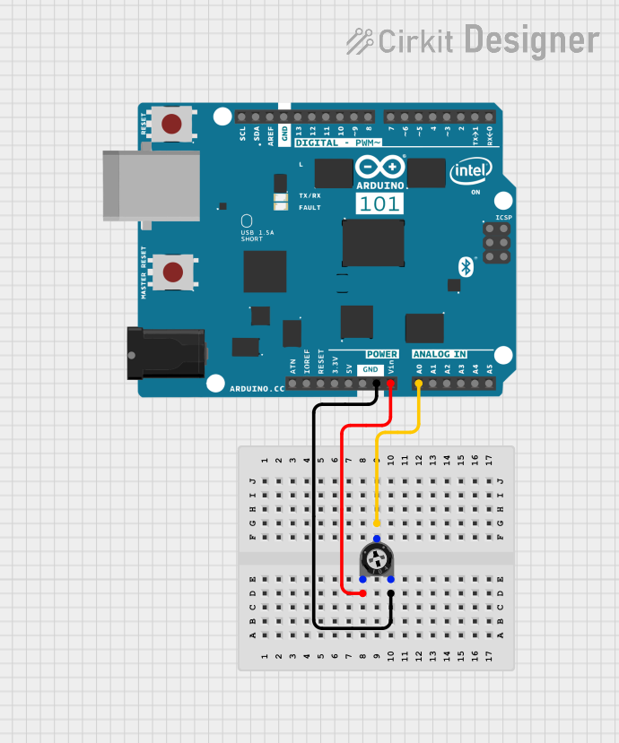
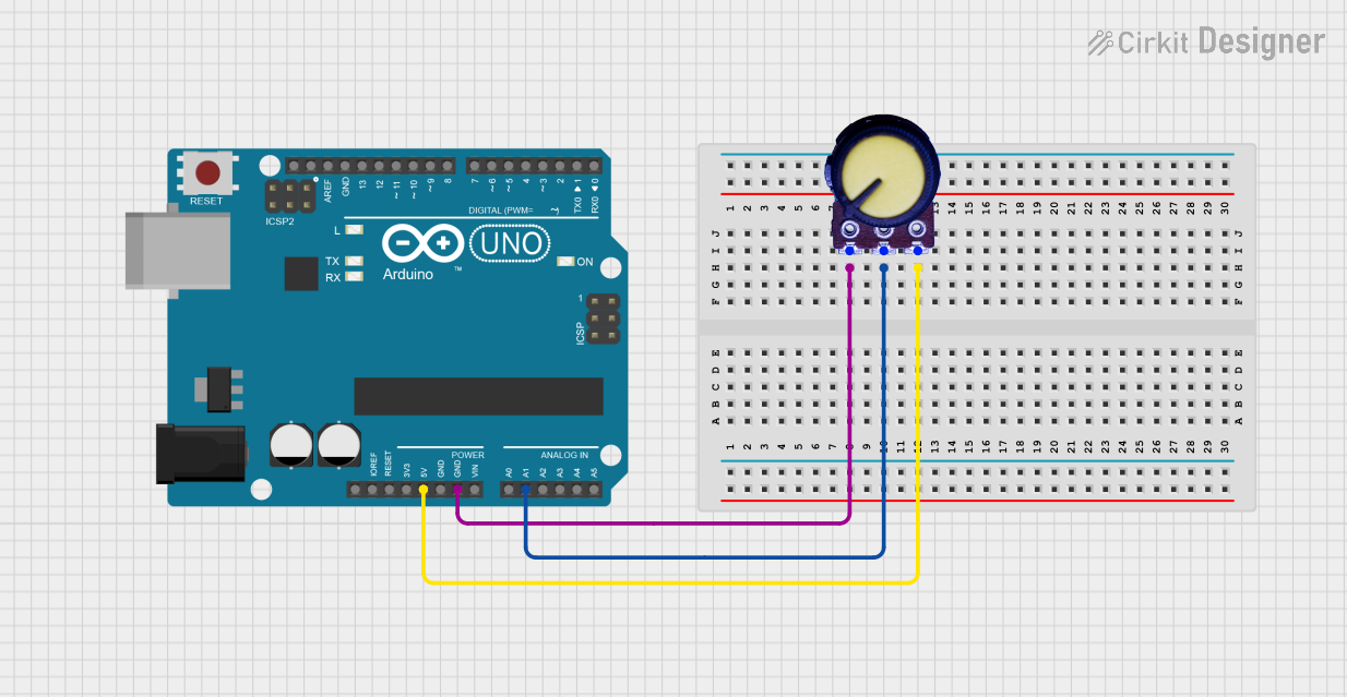
Explore Projects Built with Vout
Common Applications and Use Cases
- Power Supply Units (PSUs): Vout is the regulated voltage provided to electronic devices.
- Voltage Regulators: These components maintain a constant Vout despite variations in input voltage or load conditions.
- Amplifiers: In audio and signal amplifiers, Vout is the amplified version of the input signal.
- Microcontrollers & Development Boards: Vout from a digital pin can be used to drive LEDs, transistors, and other components.
Technical Specifications
Since Vout is a parameter rather than a physical component, the technical specifications will vary depending on the circuit or device generating the Vout. Below is a generic table that could represent the specifications for a voltage regulator component, which provides a Vout:
| Parameter | Description | Min | Typ | Max | Unit |
|---|---|---|---|---|---|
| Output Voltage (Vout) | Regulated output voltage | 1.8 | 3.3 | 5.0 | V |
| Output Current | Maximum current the Vout can provide | - | - | 1.5 | A |
| Load Regulation | Change in Vout with varying load | - | ±0.5 | ±2 | % |
| Line Regulation | Change in Vout with varying input voltage | - | ±0.2 | ±1 | % |
| Ripple & Noise | Peak-to-peak voltage variations at Vout | - | - | 50 | mVpp |
Note: The above table is illustrative and should be replaced with the actual specifications of the device or circuit in question.
Usage Instructions
How to Use Vout in a Circuit
- Identify the Required Vout: Determine the voltage level needed for your load or circuit.
- Select a Power Source: Choose a power source or voltage regulator that can provide the required Vout.
- Connect the Load: Ensure the load is properly connected to the Vout terminal of the power source or regulator.
- Verify Vout: Use a multimeter to measure the Vout and confirm it matches the desired voltage level.
Important Considerations and Best Practices
- Voltage Compatibility: Ensure the Vout is compatible with the voltage requirements of the load.
- Current Limitations: Do not exceed the current rating of the power source or regulator providing Vout.
- Heat Dissipation: Be aware of heat generated due to voltage regulation and provide adequate cooling if necessary.
- Filtering: To minimize ripple and noise, use capacitors and other filtering components as required.
Troubleshooting and FAQs
Common Issues
- Incorrect Vout: If the measured Vout is not within specifications, check the input voltage, load connections, and any adjustable settings on the voltage regulator.
- Overheating: Excessive heat can be a sign of overcurrent or insufficient cooling. Ensure the current draw is within limits and improve heat dissipation.
- Voltage Fluctuations: Voltage fluctuations can be caused by an unstable input voltage or a varying load. Use proper filtering and regulation to stabilize Vout.
FAQs
Q: What happens if my Vout is too high or too low? A: An incorrect Vout can lead to poor performance or damage to the load. Always adjust the Vout to match the required voltage level.
Q: Can I use a voltage divider to create a specific Vout? A: Yes, a voltage divider can be used for low-power applications, but it is not recommended for variable loads or when precise regulation is needed.
Q: How can I increase the current capacity of my Vout? A: To increase current capacity, use a power source or regulator with a higher current rating, or parallel multiple regulators while ensuring proper load sharing.
Example Code for Arduino UNO
Here's an example of how to set a digital pin to HIGH, providing a Vout of approximately 5V on an Arduino UNO:
// Define the pin connected to the load
const int outputPin = 8;

void setup() {
  // Set the pin as an output
  pinMode(outputPin, OUTPUT);
}

void loop() {
  // Set the pin to HIGH, providing Vout to the load
  digitalWrite(outputPin, HIGH);

  // Add your code here to control when to turn off the Vout
}
Note: The actual Vout from an Arduino digital pin may vary slightly from the nominal 5V due to the board's voltage regulator and the current drawn by the load.