
How to Use solenoid electrovalve: Examples, Pinouts, and Specs
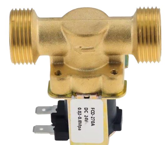
 Design with solenoid electrovalve in Cirkit Designer
Introduction
A solenoid electrovalve is an electromechanical device that controls the flow of fluids or gases. It operates by using an electromagnetic solenoid to open or close a valve, enabling precise control over the flow. These valves are widely used in applications such as irrigation systems, industrial automation, HVAC systems, and medical devices. Their ability to provide reliable and efficient control makes them a critical component in many fluid and gas management systems.
Explore Projects Built with solenoid electrovalve
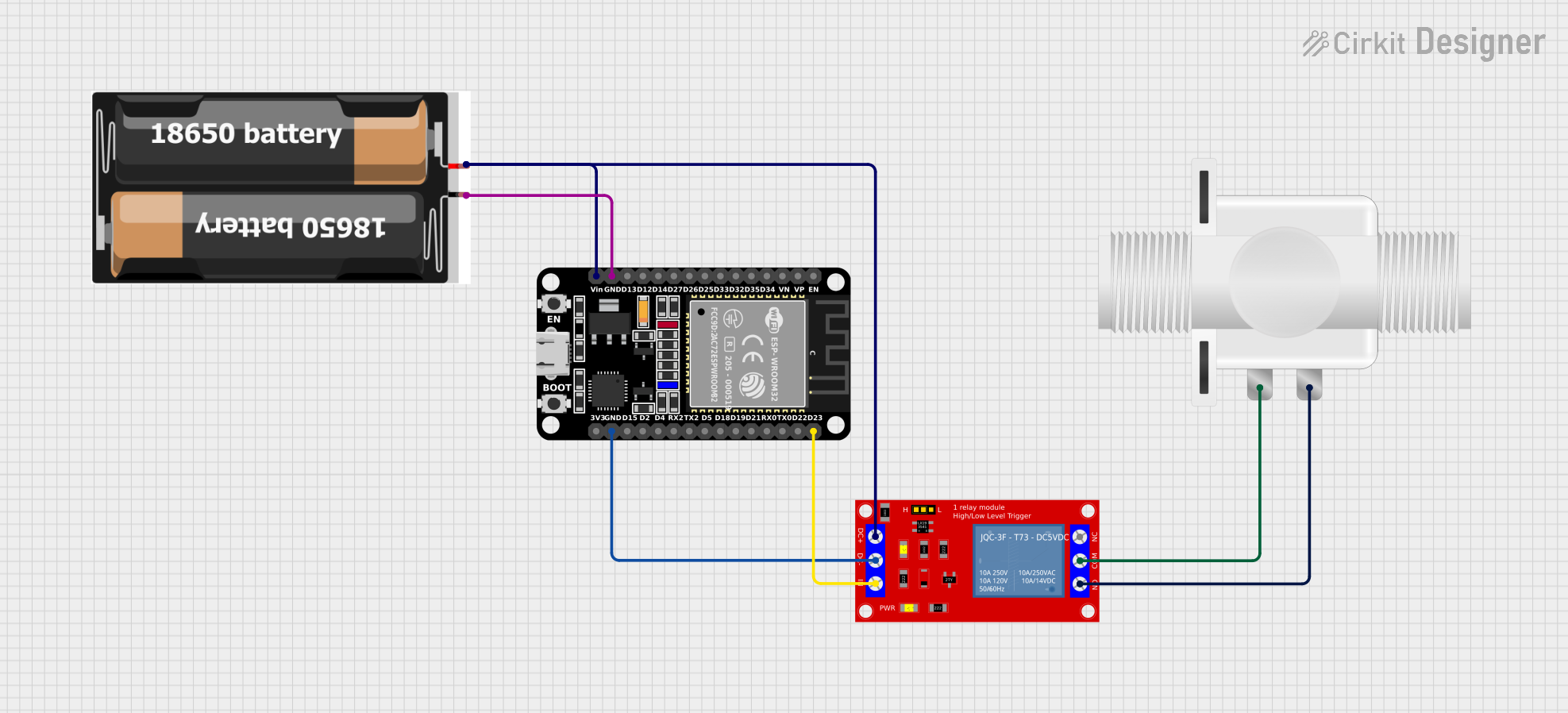 Open Project in Cirkit Designer
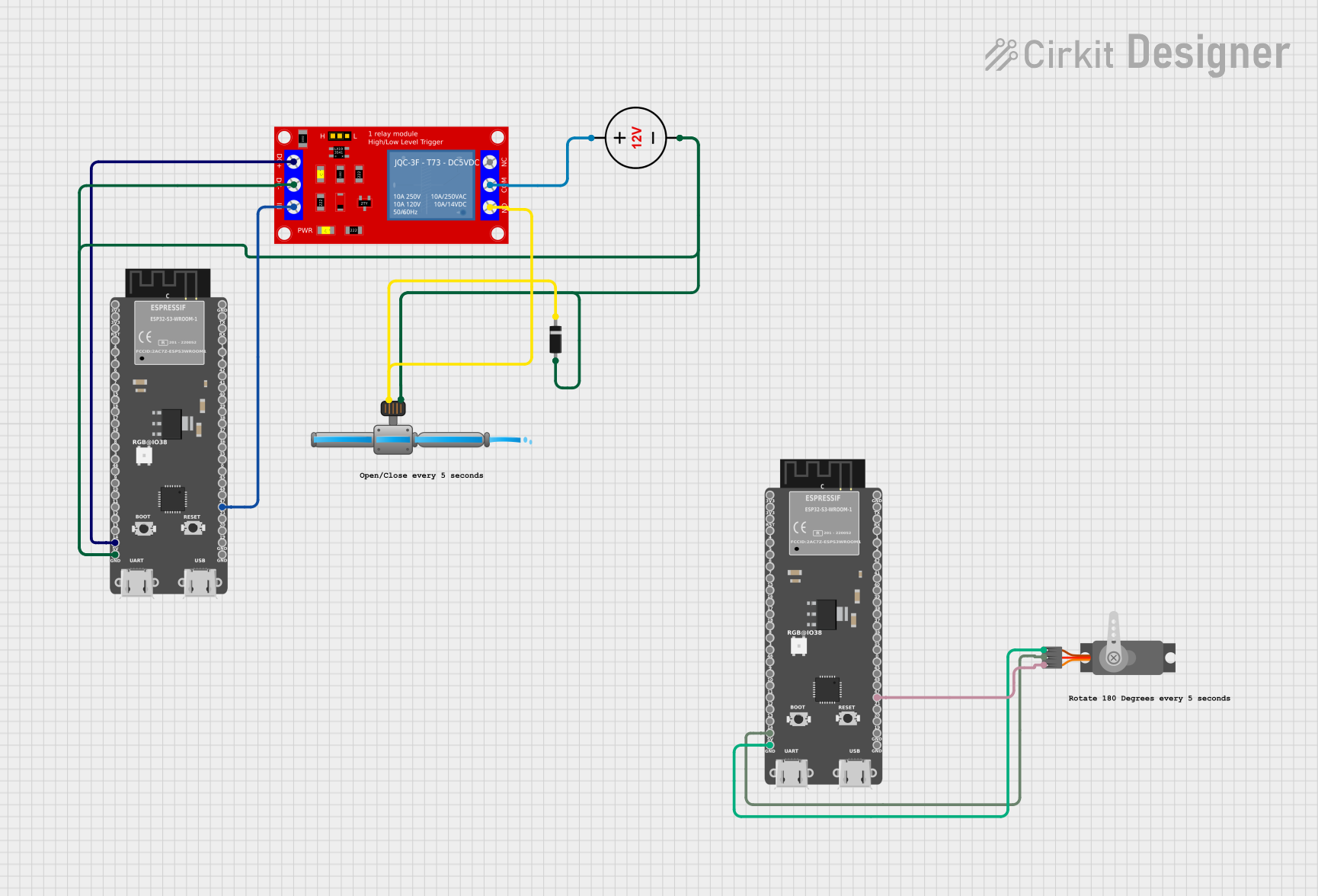 Open Project in Cirkit Designer
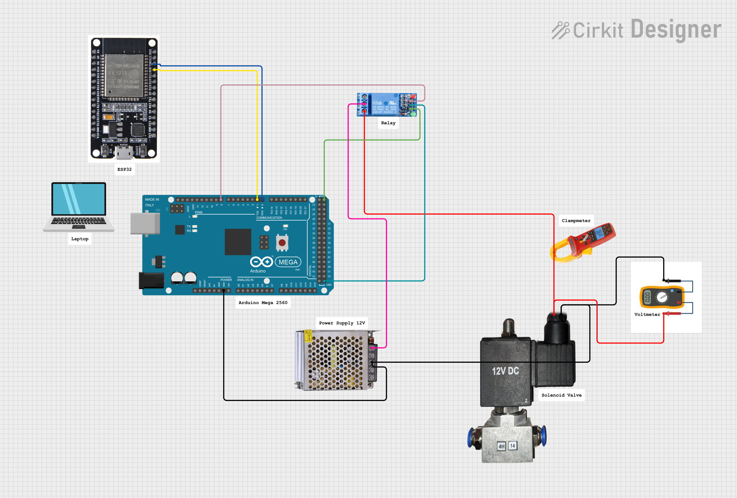 Open Project in Cirkit Designer
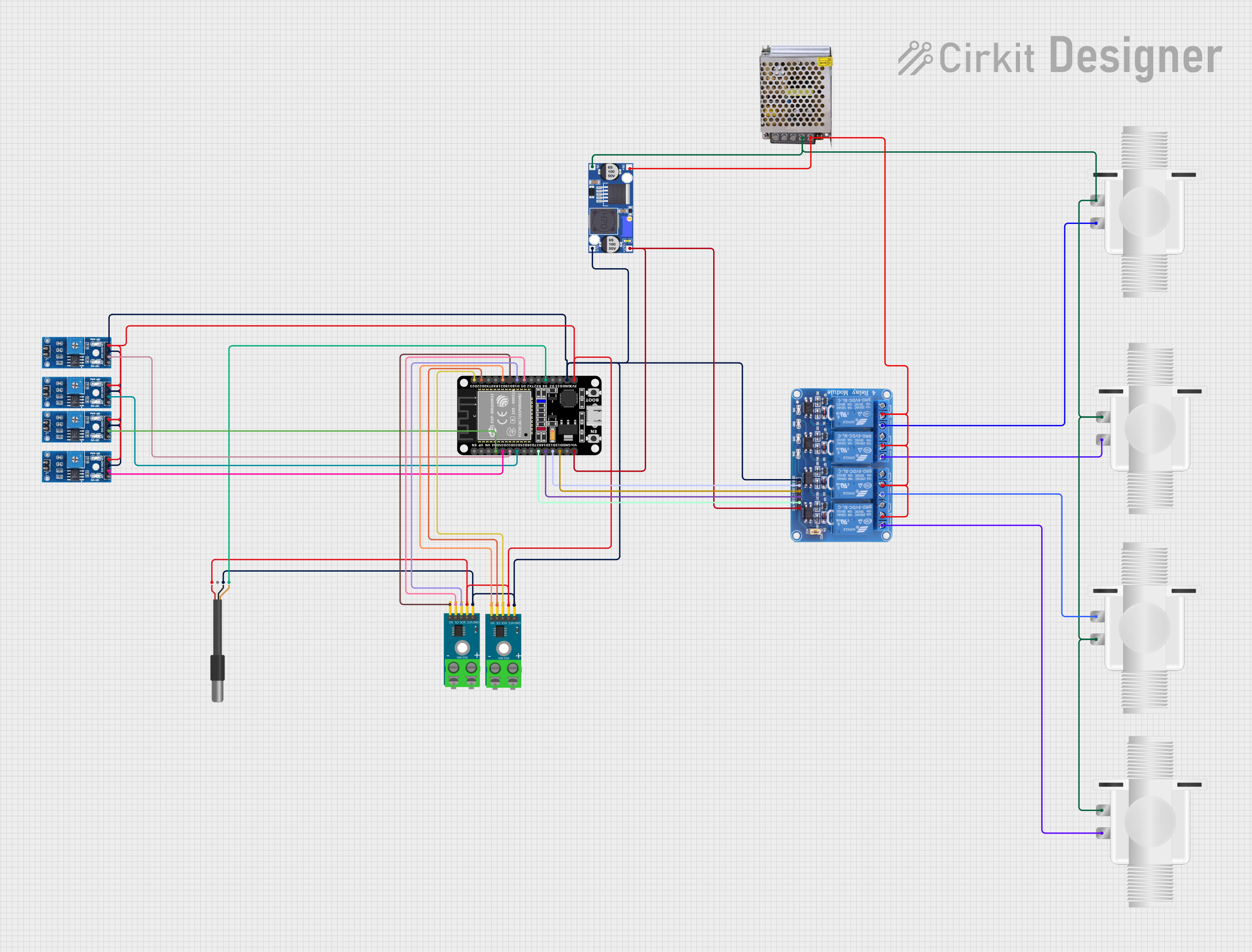 Open Project in Cirkit Designer
Explore Projects Built with solenoid electrovalve
Open Project in Cirkit DesignerOpen Project in Cirkit DesignerOpen Project in Cirkit DesignerOpen Project in Cirkit DesignerTechnical Specifications
Below are the key technical details for a typical solenoid electrovalve. Note that specifications may vary depending on the specific model or manufacturer.
General Specifications
- Operating Voltage: 12V DC or 24V DC (common variants)
- Current Consumption: 0.2A to 0.5A (depending on valve size and type)
- Power Rating: 2W to 12W
- Operating Pressure Range: 0.1 to 10 bar
- Flow Rate: 0.1 to 20 liters per minute (varies by model)
- Material: Brass, stainless steel, or plastic (depending on application)
- Temperature Range: -10°C to 80°C (fluid-dependent)
Pin Configuration and Descriptions
The solenoid electrovalve typically has two electrical terminals for connection. Below is a table describing the pin configuration:
| Pin Number | Label | Description |
|---|---|---|
| 1 | Positive (+) | Connect to the positive terminal of the power supply. |
| 2 | Negative (-) | Connect to the negative terminal (ground). |
Note: Some solenoid electrovalves may include additional terminals for advanced features, such as feedback signals or manual override. Refer to the specific datasheet for details.
Usage Instructions
How to Use the Solenoid Electrovalve in a Circuit
- Power Supply: Ensure the power supply matches the operating voltage of the solenoid electrovalve (e.g., 12V DC or 24V DC). Use a regulated power source to avoid voltage fluctuations.
- Wiring:
- Connect the positive terminal of the power supply to the positive (+) pin of the solenoid.
- Connect the negative terminal of the power supply to the negative (-) pin of the solenoid.
- Control: Use a switch, relay, or transistor to control the solenoid. For microcontroller-based systems (e.g., Arduino), use a transistor or MOSFET to handle the current requirements of the solenoid.
- Diode Protection: Place a flyback diode across the solenoid terminals to protect the circuit from voltage spikes caused by the collapsing magnetic field when the solenoid is turned off.
Example: Connecting to an Arduino UNO
Below is an example of how to control a 12V solenoid electrovalve using an Arduino UNO and an NPN transistor (e.g., 2N2222):
Circuit Components
- 1x Solenoid Electrovalve (12V)
- 1x NPN Transistor (e.g., 2N2222)
- 1x Flyback Diode (e.g., 1N4007)
- 1x Resistor (1kΩ)
- 1x External 12V Power Supply
Circuit Diagram
Arduino Pin D9 ----> 1kΩ Resistor ----> Base of Transistor
Collector of Transistor ----> Negative (-) Pin of Solenoid
Emitter of Transistor ----> Ground
Positive (+) Pin of Solenoid ----> 12V Power Supply Positive
12V Power Supply Negative ----> Ground
Flyback Diode: Cathode to Positive (+) Pin of Solenoid, Anode to Negative (-) Pin
Arduino Code
// Define the pin connected to the transistor base
const int solenoidPin = 9;

void setup() {
  pinMode(solenoidPin, OUTPUT); // Set the solenoid pin as an output
}

void loop() {
  digitalWrite(solenoidPin, HIGH); // Turn the solenoid ON
  delay(1000);                     // Keep it ON for 1 second
  digitalWrite(solenoidPin, LOW);  // Turn the solenoid OFF
  delay(1000);                     // Keep it OFF for 1 second
}
Important Considerations and Best Practices
- Voltage Matching: Always ensure the solenoid's operating voltage matches the power supply.
- Current Handling: Use components (e.g., transistors, relays) that can handle the solenoid's current requirements.
- Flyback Diode: Always include a flyback diode to protect the circuit from voltage spikes.
- Heat Dissipation: Ensure proper ventilation or heat sinking if the solenoid operates continuously for long periods.
- Fluid Compatibility: Verify that the solenoid's materials are compatible with the fluid or gas being controlled.
Troubleshooting and FAQs
Common Issues and Solutions
Solenoid Does Not Activate:
- Check the power supply voltage and ensure it matches the solenoid's requirements.
- Verify all connections, especially the positive and negative terminals.
- Ensure the control circuit (e.g., transistor or relay) is functioning correctly.
Overheating:
- Ensure the solenoid is not powered continuously for longer than its rated duty cycle.
- Check for proper ventilation or heat dissipation.
Fluid Leakage:
- Inspect the valve for physical damage or debris.
- Ensure the solenoid is installed correctly and tightened securely.
Voltage Spikes in Circuit:
- Confirm that a flyback diode is installed across the solenoid terminals.
FAQs
Q: Can I use a solenoid electrovalve with an AC power supply?
A: Some solenoid electrovalves are designed for AC operation, but this documentation focuses on DC variants. Check the product specifications to confirm compatibility.
Q: What happens if I reverse the polarity of the solenoid connections?
A: Reversing polarity may damage the solenoid or prevent it from functioning. Always connect the positive and negative terminals correctly.
Q: Can I control multiple solenoid valves with one Arduino?
A: Yes, you can control multiple solenoids using separate pins and transistors or relays. Ensure the Arduino and power supply can handle the total current draw.
Q: How do I clean a solenoid electrovalve?
A: Disconnect the valve from the power supply and fluid system. Disassemble it carefully and clean the internal components with a compatible cleaning solution. Reassemble and test before reinstalling.
This documentation provides a comprehensive guide to understanding, using, and troubleshooting solenoid electrovalves. Always refer to the specific datasheet for your model for additional details.