Cirkit Designer Logo
Cirkit Designer
Your all-in-one circuit design IDE
Home / 
Component Documentation

How to Use IR TX: Examples, Pinouts, and Specs

Image of IR TX
Cirkit Designer LogoDesign with IR TX in Cirkit Designer

Introduction

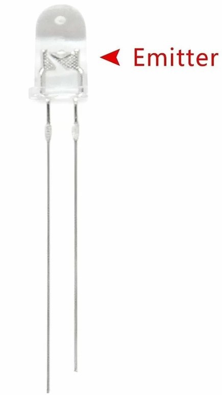
An infrared transmitter (IR TX) is a device that emits infrared light, typically used for wireless communication and remote control applications. IR transmitters are commonly found in remote controls for televisions, air conditioners, and other consumer electronics. They are also used in various communication systems, sensors, and automation projects.

Explore Projects Built with IR TX

Use Cirkit Designer to design, explore, and prototype these projects online. Some projects support real-time simulation. Click "Open Project" to start designing instantly!
Arduino UNO-Based IR Transmitter with Multiple Pushbutton Controls and Battery Power
Image of 38 khz ir sensor remote: A project utilizing IR TX in a practical application
This circuit is an IR transmitter system controlled by an Arduino UNO, powered by a 3.7V LiPo battery through a rocker switch. It includes multiple pushbuttons connected to the Arduino's digital pins, which likely serve as inputs to control the IR transmission, with a BC547 transistor used to drive the IR LED.
Cirkit Designer LogoOpen Project in Cirkit Designer
Satellite-Based Timing and Navigation System with SDR and Atomic Clock Synchronization
Image of GPS 시스템 측정 구성도_Confirm: A project utilizing IR TX in a practical application
This circuit appears to be a complex system involving power supply management, GPS and timing synchronization, and data communication. It includes a SI-TEX G1 Satellite Compass for GPS data, an XHTF1021 Atomic Rubidium Clock for precise timing, and Ettus USRP B200 units for software-defined radio communication. Power is supplied through various SMPS units and distributed via terminal blocks and DC jacks. Data communication is facilitated by Beelink MINI S12 N95 computers, RS232 splitters, and a 1000BASE-T Media Converter for network connectivity. RF Directional Couplers are used to interface antennas with the USRP units, and the entire system is likely contained within cases for protection and organization.
Cirkit Designer LogoOpen Project in Cirkit Designer
ESP-01 Based IR Remote Control Receiver
Image of Stock: A project utilizing IR TX in a practical application
This circuit consists of an ESP-01 microcontroller connected to an IR receiver. The ESP-01 is configured to receive data from the IR receiver through its GPIO0 pin, and both components share a common ground and power connection. The provided code for the ESP-01 microcontroller is a template with empty setup and loop functions, indicating that the specific functionality for the IR data processing has not been implemented yet.
Cirkit Designer LogoOpen Project in Cirkit Designer
ESP32-Based Portable Smart Speaker with Audio Input Processing
Image of talkAI: A project utilizing IR TX in a practical application
This circuit features two ESP32 microcontrollers configured for serial communication, with one ESP32's TX0 connected to the other's RX2, and vice versa. An INMP441 microphone is interfaced with one ESP32 for audio input, using I2S protocol with connections for serial clock (SCK), word select (WS), and serial data (SD). A Max98357 audio amplifier is connected to the other ESP32 to drive a loudspeaker, receiving I2S data (DIN), bit clock (BLCK), and left-right clock (LRC), and is powered by a lipo battery charger module.
Cirkit Designer LogoOpen Project in Cirkit Designer

Explore Projects Built with IR TX

Use Cirkit Designer to design, explore, and prototype these projects online. Some projects support real-time simulation. Click "Open Project" to start designing instantly!
Image of 38 khz ir sensor remote: A project utilizing IR TX in a practical application
Arduino UNO-Based IR Transmitter with Multiple Pushbutton Controls and Battery Power
This circuit is an IR transmitter system controlled by an Arduino UNO, powered by a 3.7V LiPo battery through a rocker switch. It includes multiple pushbuttons connected to the Arduino's digital pins, which likely serve as inputs to control the IR transmission, with a BC547 transistor used to drive the IR LED.
Cirkit Designer LogoOpen Project in Cirkit Designer
Image of GPS 시스템 측정 구성도_Confirm: A project utilizing IR TX in a practical application
Satellite-Based Timing and Navigation System with SDR and Atomic Clock Synchronization
This circuit appears to be a complex system involving power supply management, GPS and timing synchronization, and data communication. It includes a SI-TEX G1 Satellite Compass for GPS data, an XHTF1021 Atomic Rubidium Clock for precise timing, and Ettus USRP B200 units for software-defined radio communication. Power is supplied through various SMPS units and distributed via terminal blocks and DC jacks. Data communication is facilitated by Beelink MINI S12 N95 computers, RS232 splitters, and a 1000BASE-T Media Converter for network connectivity. RF Directional Couplers are used to interface antennas with the USRP units, and the entire system is likely contained within cases for protection and organization.
Cirkit Designer LogoOpen Project in Cirkit Designer
Image of Stock: A project utilizing IR TX in a practical application
ESP-01 Based IR Remote Control Receiver
This circuit consists of an ESP-01 microcontroller connected to an IR receiver. The ESP-01 is configured to receive data from the IR receiver through its GPIO0 pin, and both components share a common ground and power connection. The provided code for the ESP-01 microcontroller is a template with empty setup and loop functions, indicating that the specific functionality for the IR data processing has not been implemented yet.
Cirkit Designer LogoOpen Project in Cirkit Designer
Image of talkAI: A project utilizing IR TX in a practical application
ESP32-Based Portable Smart Speaker with Audio Input Processing
This circuit features two ESP32 microcontrollers configured for serial communication, with one ESP32's TX0 connected to the other's RX2, and vice versa. An INMP441 microphone is interfaced with one ESP32 for audio input, using I2S protocol with connections for serial clock (SCK), word select (WS), and serial data (SD). A Max98357 audio amplifier is connected to the other ESP32 to drive a loudspeaker, receiving I2S data (DIN), bit clock (BLCK), and left-right clock (LRC), and is powered by a lipo battery charger module.
Cirkit Designer LogoOpen Project in Cirkit Designer

Technical Specifications

Key Technical Details

Parameter Value
Operating Voltage 2.7V to 5.5V
Operating Current 20mA to 50mA
Wavelength 850nm to 950nm
Emission Angle 20° to 60°
Peak Emission 940nm
Modulation 38kHz (common for remote control)

Pin Configuration and Descriptions

Pin Number Pin Name Description
1 Anode Connect to positive supply voltage
2 Cathode Connect to ground

Usage Instructions

How to Use the Component in a Circuit

  1. Power Supply: Connect the anode (Pin 1) to the positive supply voltage (2.7V to 5.5V).
  2. Ground Connection: Connect the cathode (Pin 2) to the ground.
  3. Control Signal: Use a microcontroller (e.g., Arduino) to modulate the IR signal. The control signal should be a 38kHz square wave for typical remote control applications.

Important Considerations and Best Practices

  • Current Limiting Resistor: Use a current-limiting resistor in series with the anode to prevent excessive current draw. Calculate the resistor value using Ohm's Law: ( R = \frac{V_{supply} - V_{forward}}{I_{forward}} ).
  • Modulation: Ensure the IR signal is modulated at the correct frequency (38kHz) for compatibility with most IR receivers.
  • Line of Sight: IR communication requires a clear line of sight between the transmitter and receiver. Avoid obstacles that can block the IR signal.

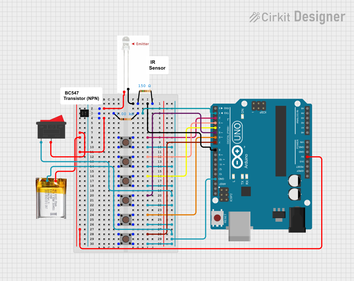
Example Circuit with Arduino UNO

/*
 * Example code to control an IR transmitter using Arduino UNO.
 * This code generates a 38kHz modulated signal on pin 3.
 */

const int irPin = 3; // IR transmitter connected to digital pin 3

void setup() {
  pinMode(irPin, OUTPUT); // Set the IR pin as an output
}

void loop() {
  // Generate a 38kHz signal
  for (int i = 0; i < 100; i++) { // Adjust the loop count for desired duration
    digitalWrite(irPin, HIGH);
    delayMicroseconds(13); // 13us high time for 38kHz
    digitalWrite(irPin, LOW);
    delayMicroseconds(13); // 13us low time for 38kHz
  }
  delay(1000); // Wait for 1 second before repeating
}

Troubleshooting and FAQs

Common Issues Users Might Face

  1. No Signal Emission: Ensure the IR transmitter is connected correctly and receiving the appropriate voltage. Check for loose connections and verify the current-limiting resistor value.
  2. Weak Signal: Verify that the IR transmitter is not obstructed and that the emission angle is aligned with the receiver. Check the power supply voltage and current.
  3. Incorrect Modulation: Ensure the control signal is modulated at 38kHz. Use an oscilloscope to verify the signal frequency if necessary.

Solutions and Tips for Troubleshooting

  • Check Connections: Double-check all connections to ensure they are secure and correct.
  • Verify Power Supply: Ensure the power supply voltage is within the specified range (2.7V to 5.5V).
  • Use Proper Resistor: Calculate and use the correct current-limiting resistor to prevent damage to the IR transmitter.
  • Test with Known Good Components: If possible, test the IR transmitter with a known good receiver to isolate the issue.

FAQs

Q1: Can I use the IR transmitter with a different modulation frequency? A1: Yes, but ensure the receiver is compatible with the chosen frequency. 38kHz is standard for most remote control applications.

Q2: How can I increase the range of the IR transmitter? A2: Use a higher power IR LED and ensure a clear line of sight. Increasing the supply voltage within the specified range can also help.

Q3: Can I use multiple IR transmitters in the same circuit? A3: Yes, but ensure each transmitter has its own current-limiting resistor and is properly modulated.

By following this documentation, users should be able to effectively utilize the IR transmitter in their projects, ensuring reliable and efficient wireless communication.