How to Use LoRa XL1278-SMT: Examples, Pinouts, and Specs
Introduction
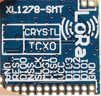
The LoRa XL1278-SMT is a low-power, long-range transceiver module designed for wireless communication in Internet of Things (IoT) applications. Operating in the 433 MHz frequency band, it utilizes LoRa modulation technology to achieve robust and reliable data transmission over distances of several kilometers, even in environments with significant interference. Its compact size and surface-mount design make it ideal for integration into a wide range of electronic projects, including smart agriculture, industrial automation, and remote monitoring systems.
Explore Projects Built with LoRa XL1278-SMT


Explore Projects Built with LoRa XL1278-SMT
Common Applications
- Smart agriculture (e.g., soil moisture monitoring, weather stations)
- Industrial automation and control systems
- Remote environmental monitoring
- Home automation and security systems
- Wireless sensor networks
- Asset tracking and geolocation
Technical Specifications
Key Technical Details
| Parameter | Value |
|---|---|
| Frequency Band | 433 MHz |
| Modulation Technique | LoRa |
| Communication Range | Up to 5 km (line of sight) |
| Supply Voltage | 1.8V to 3.7V |
| Operating Current | 10.8 mA (transmit mode) |
| Sleep Current | < 1 µA |
| Data Rate | 0.3 kbps to 37.5 kbps |
| Sensitivity | -139 dBm |
| Output Power | Up to +20 dBm |
| Operating Temperature | -40°C to +85°C |
| Dimensions | 17.8 mm x 12.8 mm x 2.3 mm |
Pin Configuration and Descriptions
| Pin Number | Pin Name | Description |
|---|---|---|
| 1 | GND | Ground connection |
| 2 | VCC | Power supply input (1.8V to 3.7V) |
| 3 | DIO0 | Digital I/O pin 0, used for interrupt signaling |
| 4 | DIO1 | Digital I/O pin 1, configurable for various functions |
| 5 | DIO2 | Digital I/O pin 2, configurable for various functions |
| 6 | MISO | SPI Master-In-Slave-Out (data output from module) |
| 7 | MOSI | SPI Master-Out-Slave-In (data input to module) |
| 8 | SCK | SPI clock input |
| 9 | NSS | SPI chip select (active low) |
| 10 | RESET | Reset pin, active low |
Usage Instructions
How to Use the Component in a Circuit
- Power Supply: Connect the VCC pin to a regulated power source (1.8V to 3.7V) and the GND pin to the ground of your circuit.
- SPI Communication: Connect the SPI pins (MISO, MOSI, SCK, NSS) to the corresponding pins on your microcontroller. Ensure proper configuration of the SPI interface.
- Interrupts: Use the DIO pins for interrupt-driven communication or other configurable functions as needed.
- Antenna: Attach a 433 MHz antenna to the module for optimal signal transmission and reception.
- Reset: Connect the RESET pin to your microcontroller or a manual reset circuit for initializing the module.
Important Considerations and Best Practices
- Antenna Placement: Ensure the antenna is placed away from metal objects and other sources of interference to maximize range.
- Power Supply: Use a low-noise, stable power supply to avoid communication errors.
- SPI Configuration: Set the SPI clock speed and mode according to the module's requirements (typically SPI Mode 0).
- Heat Management: Operate the module within the specified temperature range to prevent damage.
- Regulatory Compliance: Ensure compliance with local regulations for the 433 MHz frequency band.
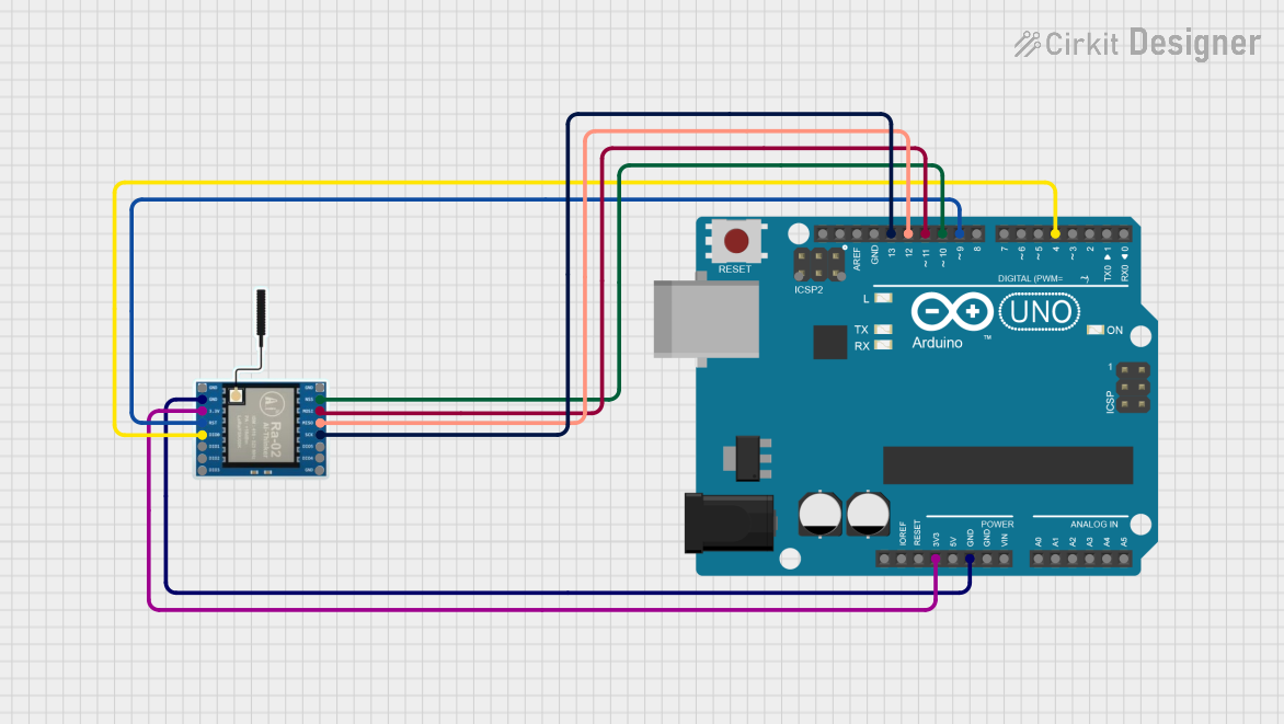
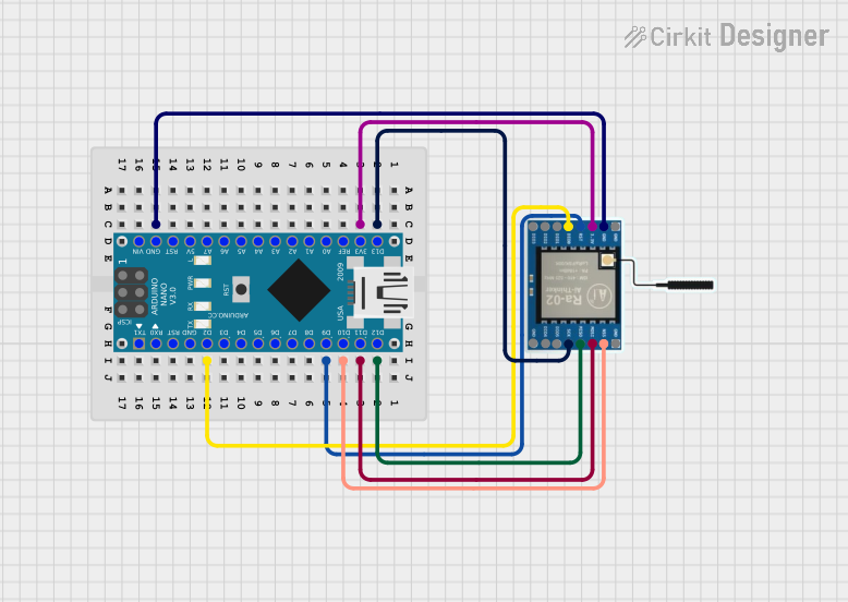
Example Code for Arduino UNO
Below is an example of how to interface the LoRa XL1278-SMT with an Arduino UNO using the popular LoRa library.
#include <SPI.h>
#include <LoRa.h>

// Define LoRa module pins
#define NSS 10    // SPI chip select pin
#define RESET 9   // Reset pin
#define DIO0 2    // Interrupt pin

void setup() {
  // Initialize serial communication for debugging
  Serial.begin(9600);
  while (!Serial);

  Serial.println("Initializing LoRa module...");

  // Initialize LoRa module
  LoRa.setPins(NSS, RESET, DIO0); // Set SPI and control pins
  if (!LoRa.begin(433E6)) {       // Initialize at 433 MHz
    Serial.println("LoRa initialization failed!");
    while (1);
  }

  Serial.println("LoRa initialized successfully!");
}

void loop() {
  // Send a test message
  Serial.println("Sending message...");
  LoRa.beginPacket();            // Start a new packet
  LoRa.print("Hello, LoRa!");    // Add data to the packet
  LoRa.endPacket();              // Send the packet

  delay(5000);                   // Wait 5 seconds before sending again
}
Notes on the Code
- Ensure the
LoRalibrary is installed in your Arduino IDE. You can install it via the Library Manager. - Modify the pin definitions (
NSS,RESET,DIO0) if you are using different connections. - Adjust the frequency (
433E6) if you are using a different frequency band.
Troubleshooting and FAQs
Common Issues and Solutions
Module Not Responding
- Cause: Incorrect wiring or power supply issues.
- Solution: Double-check all connections and ensure the power supply voltage is within the specified range.
Poor Communication Range
- Cause: Improper antenna placement or interference.
- Solution: Use a high-quality 433 MHz antenna and place it away from obstructions or interference sources.
Data Transmission Errors
- Cause: SPI misconfiguration or noisy power supply.
- Solution: Verify SPI settings (clock speed, mode) and use a stable power source.
Module Overheating
- Cause: Operating outside the specified temperature range or excessive output power.
- Solution: Ensure proper heat dissipation and operate within the recommended temperature range.
FAQs
Q: Can the LoRa XL1278-SMT be used with 5V microcontrollers?
A: The module operates at 1.8V to 3.7V. Use a level shifter to interface with 5V microcontrollers.
Q: What is the maximum data rate supported?
A: The module supports data rates from 0.3 kbps to 37.5 kbps, depending on the configuration.
Q: How can I increase the communication range?
A: Use a high-gain antenna, ensure line-of-sight placement, and minimize interference in the environment.
Q: Is the module compatible with other LoRa devices?
A: Yes, as long as they operate on the same frequency band (433 MHz) and use compatible settings.