Cirkit Designer
Your all-in-one circuit design IDE
Home /
Component Documentation
How to Use BNO08x: Examples, Pinouts, and Specs
Introduction
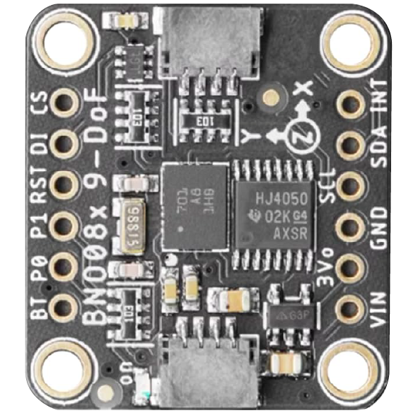
The BNO08x is a 9-axis absolute orientation sensor that integrates a 3-axis accelerometer, a 3-axis gyroscope, and a 3-axis magnetometer. It features an onboard microcontroller that performs sensor fusion, delivering highly accurate orientation data. This makes it an ideal choice for applications requiring precise motion tracking and navigation.
Explore Projects Built with BNO08x
Battery-Powered Arduino UNO with BNO085 IMU and Bluetooth HC-06 for Orientation Tracking

This circuit integrates an Arduino UNO with an Adafruit BNO085 9-DOF Orientation IMU and a Bluetooth HC-06 module. The Arduino reads orientation data from the IMU via I2C and transmits it over Bluetooth, powered by a 7.4V battery.
Arduino Nano and BNO055 Sensor with Bluetooth Connectivity
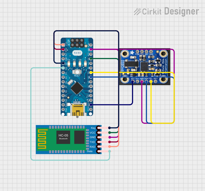
This circuit features an Arduino Nano interfaced with a BNO055 sensor and an HC-05 Bluetooth module. The Arduino communicates with the BNO055 via I2C (using A4 for SDA and A5 for SCL) and with the HC-05 via serial communication (using D0/RX and D1/TX for data transfer). The HC-05's Key and State pins are connected to D2 and D3 of the Arduino for module control, and all components share a common ground with the Arduino powered at 5V and the BNO055 at 3.3V from the Arduino's 3V3 output.
Arduino UNO-Based IMU and Bluetooth Communication System

This circuit features an Arduino UNO microcontroller interfaced with a Bluetooth HC-06 module for wireless communication and an Adafruit BNO085 9-DOF Orientation IMU for motion sensing. The Arduino handles data acquisition from the IMU via I2C and communicates the data wirelessly through the Bluetooth module.
Arduino UNO R4 WiFi Controlled Data Logger with BNO055 Sensor and Micro SD Storage
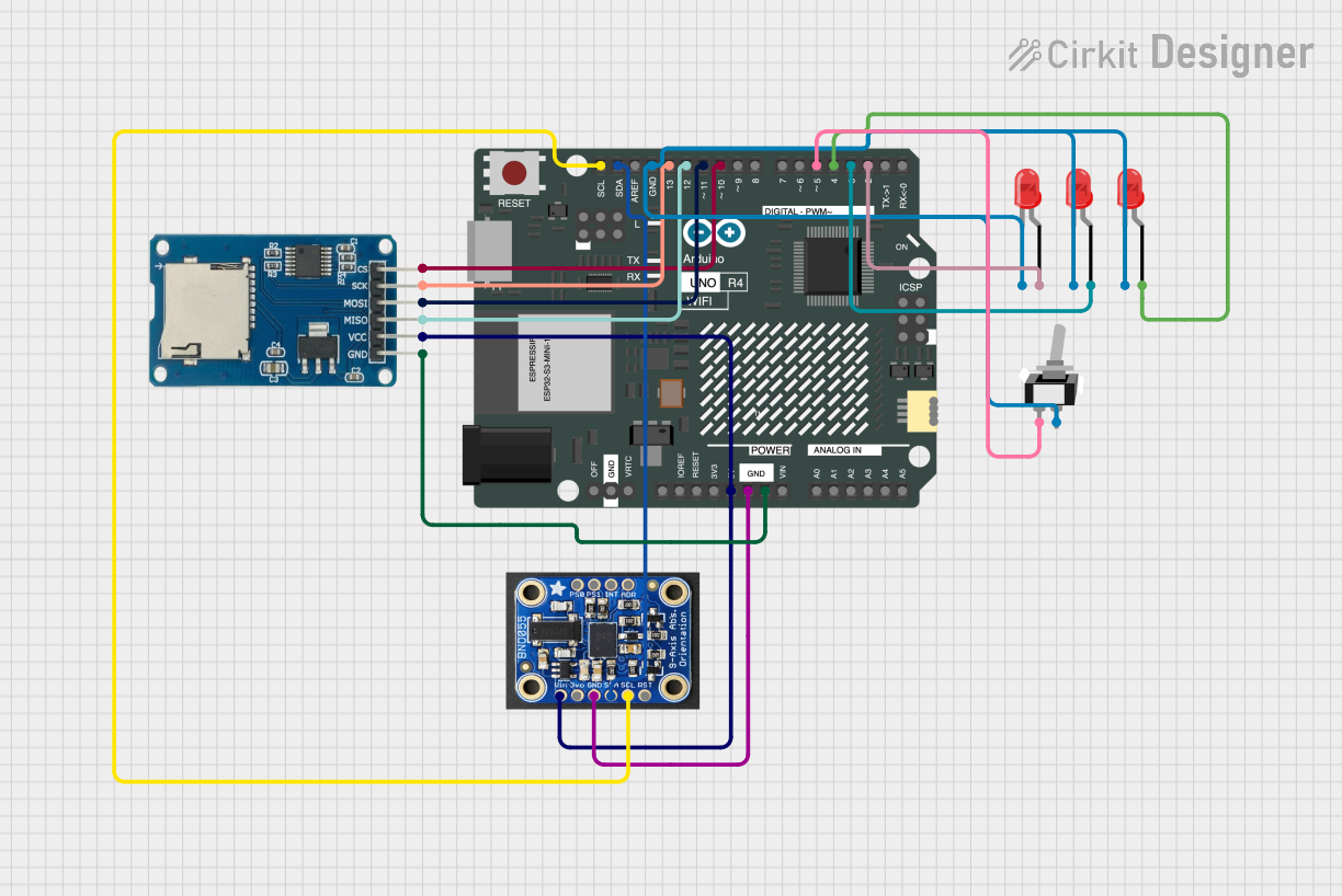
This circuit features an Arduino UNO R4 WiFi microcontroller connected to a Micro SD Card Module for data storage, a BNO055 sensor for orientation data, and three red LEDs for indication purposes. The LEDs are controlled by digital pins D2, D3, and D4, and can be turned on or off using a single-pole single-throw (SPST) toggle switch connected to their common cathodes and ground. The BNO055 sensor interfaces with the Arduino via I2C communication using the SDA and SCL pins, and the Micro SD Card Module is interfaced using SPI with chip select on pin D10 and data lines on pins D11 (MOSI), D12 (MISO), and D13 (SCK).
Explore Projects Built with BNO08x
Battery-Powered Arduino UNO with BNO085 IMU and Bluetooth HC-06 for Orientation Tracking
This circuit integrates an Arduino UNO with an Adafruit BNO085 9-DOF Orientation IMU and a Bluetooth HC-06 module. The Arduino reads orientation data from the IMU via I2C and transmits it over Bluetooth, powered by a 7.4V battery.
Arduino Nano and BNO055 Sensor with Bluetooth Connectivity
This circuit features an Arduino Nano interfaced with a BNO055 sensor and an HC-05 Bluetooth module. The Arduino communicates with the BNO055 via I2C (using A4 for SDA and A5 for SCL) and with the HC-05 via serial communication (using D0/RX and D1/TX for data transfer). The HC-05's Key and State pins are connected to D2 and D3 of the Arduino for module control, and all components share a common ground with the Arduino powered at 5V and the BNO055 at 3.3V from the Arduino's 3V3 output.
Arduino UNO-Based IMU and Bluetooth Communication System
This circuit features an Arduino UNO microcontroller interfaced with a Bluetooth HC-06 module for wireless communication and an Adafruit BNO085 9-DOF Orientation IMU for motion sensing. The Arduino handles data acquisition from the IMU via I2C and communicates the data wirelessly through the Bluetooth module.
Arduino UNO R4 WiFi Controlled Data Logger with BNO055 Sensor and Micro SD Storage
This circuit features an Arduino UNO R4 WiFi microcontroller connected to a Micro SD Card Module for data storage, a BNO055 sensor for orientation data, and three red LEDs for indication purposes. The LEDs are controlled by digital pins D2, D3, and D4, and can be turned on or off using a single-pole single-throw (SPST) toggle switch connected to their common cathodes and ground. The BNO055 sensor interfaces with the Arduino via I2C communication using the SDA and SCL pins, and the Micro SD Card Module is interfaced using SPI with chip select on pin D10 and data lines on pins D11 (MOSI), D12 (MISO), and D13 (SCK).
Common Applications
- Robotics for motion tracking and control
- Drones for stabilization and navigation
- Mobile devices for augmented reality and gaming
- Wearable devices for fitness tracking and gesture recognition
- Industrial automation and control systems
Technical Specifications
Key Technical Details
| Parameter | Value |
|---|---|
| Operating Voltage | 1.8V to 3.6V |
| Communication Interfaces | I²C, SPI, UART |
| Accelerometer Range | ±2g, ±4g, ±8g, ±16g |
| Gyroscope Range | ±125°/s, ±250°/s, ±500°/s, ±1000°/s |
| Magnetometer Range | ±1300 µT |
| Output Data Rate (ODR) | Configurable, up to 800 Hz |
| Power Consumption | ~1.3 mA (typical, varies with mode) |
| Operating Temperature | -40°C to +85°C |
| Package Type | LGA-28 (4.5 mm x 4.5 mm x 1.1 mm) |
Pin Configuration and Descriptions
| Pin Number | Pin Name | Description |
|---|---|---|
| 1 | VDD | Main power supply (1.8V to 3.6V) |
| 2 | VDDIO | I/O voltage supply |
| 3 | GND | Ground |
| 4 | SDA | I²C data line |
| 5 | SCL | I²C clock line |
| 6 | CS | Chip select for SPI interface |
| 7 | SDO | SPI data output |
| 8 | SDI | SPI data input |
| 9 | INT | Interrupt output |
| 10 | RST | Reset pin |
| 11-28 | NC | Not connected |
Usage Instructions
Using the BNO08x in a Circuit
- Power Supply: Connect the VDD pin to a 1.8V to 3.6V power source and the GND pin to ground. Ensure the VDDIO pin matches the logic level of your microcontroller (e.g., 3.3V or 5V).
- Communication Interface: Choose between I²C, SPI, or UART for communication. For I²C:
- Connect the SDA and SCL pins to the corresponding I²C pins on your microcontroller.
- Use pull-up resistors (typically 4.7 kΩ) on the SDA and SCL lines.
- Interrupts: Connect the INT pin to a GPIO pin on your microcontroller if you need to handle interrupts.
- Reset: Optionally, connect the RST pin to a GPIO pin for manual reset functionality.
Best Practices
- Use decoupling capacitors (e.g., 0.1 µF) near the VDD and VDDIO pins to reduce noise.
- Place the sensor away from magnetic or electromagnetic interference sources.
- Calibrate the sensor in your application environment for optimal accuracy.
- Use the onboard sensor fusion algorithms to reduce computational load on your microcontroller.
Example: Connecting the BNO08x to an Arduino UNO
The BNO08x can be connected to an Arduino UNO using the I²C interface. Below is an example code snippet to read orientation data:
#include <Wire.h>
#include <Adafruit_BNO08x.h>

// Create an instance of the BNO08x sensor
Adafruit_BNO08x bno08x;

// Define the I2C address of the BNO08x
#define BNO08X_I2C_ADDR 0x4A

void setup() {
  Serial.begin(115200); // Initialize serial communication
  Wire.begin();         // Initialize I2C communication

  // Initialize the BNO08x sensor
  if (!bno08x.begin_I2C(BNO08X_I2C_ADDR)) {
    Serial.println("Failed to initialize BNO08x! Check connections.");
    while (1); // Halt execution if initialization fails
  }

  Serial.println("BNO08x initialized successfully!");
}

void loop() {
  // Read orientation data
  sensors_event_t orientationEvent;
  if (bno08x.getEvent(&orientationEvent, Adafruit_BNO08x::SENSOR_ORIENTATION)) {
    Serial.print("Orientation: ");
    Serial.print("X: "); Serial.print(orientationEvent.orientation.x, 2);
    Serial.print(" Y: "); Serial.print(orientationEvent.orientation.y, 2);
    Serial.print(" Z: "); Serial.println(orientationEvent.orientation.z, 2);
  } else {
    Serial.println("Failed to read orientation data.");
  }

  delay(100); // Delay to limit data output rate
}
Notes
- Install the Adafruit BNO08x library in the Arduino IDE before running the code.
- Ensure the I²C address (default: 0x4A) matches your sensor's configuration.
Troubleshooting and FAQs
Common Issues
Sensor Not Detected:
- Ensure the power supply and ground connections are secure.
- Verify the I²C address and communication interface settings.
- Check for proper pull-up resistors on the I²C lines.
Inaccurate Orientation Data:
- Perform a calibration routine in the application environment.
- Avoid placing the sensor near strong magnetic fields or vibrations.
Interrupts Not Triggering:
- Confirm the INT pin is connected to a GPIO pin on the microcontroller.
- Check the interrupt configuration in your code.
Tips for Troubleshooting
- Use a logic analyzer or oscilloscope to verify communication signals.
- Test the sensor with a known working library or example code.
- Consult the BNO08x datasheet for detailed configuration options.
By following this documentation, you can effectively integrate the BNO08x into your projects and achieve accurate motion tracking and orientation sensing.