How to Use 7 semi vikram 10a: Examples, Pinouts, and Specs
Introduction
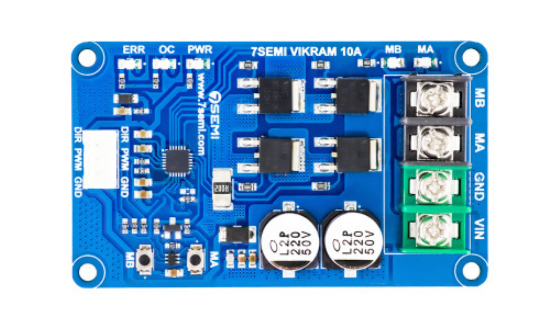
The Vikram 10A is a high-power 7-segment display driver designed to handle up to 10A of current, making it ideal for driving large LED displays or arrays. This component simplifies the process of controlling 7-segment displays by providing efficient current handling and straightforward interfacing with microcontrollers or other control circuits. Its robust design ensures reliable operation in demanding applications.
Explore Projects Built with 7 semi vikram 10a
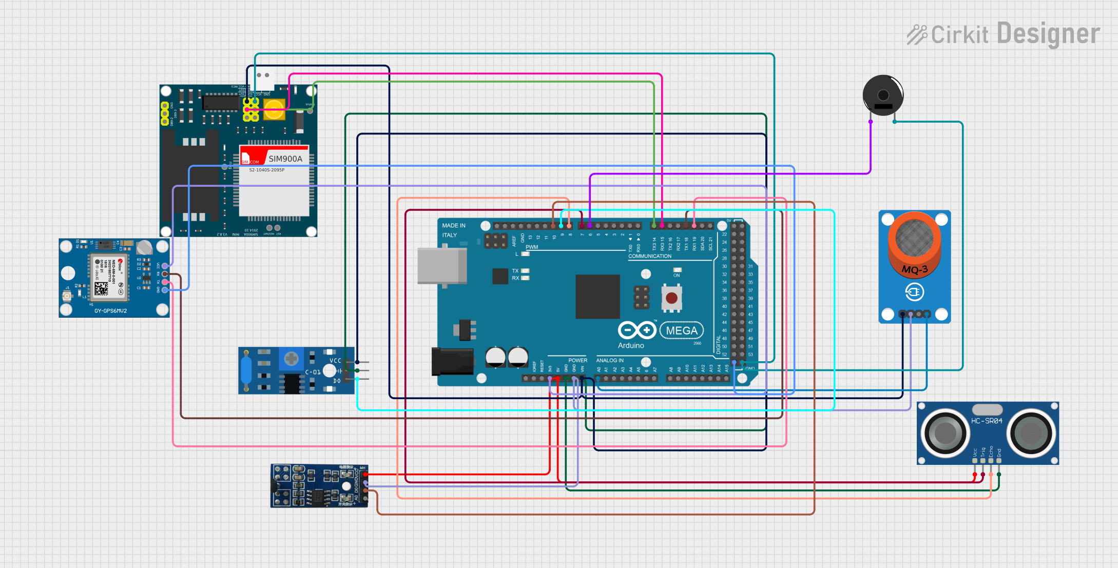
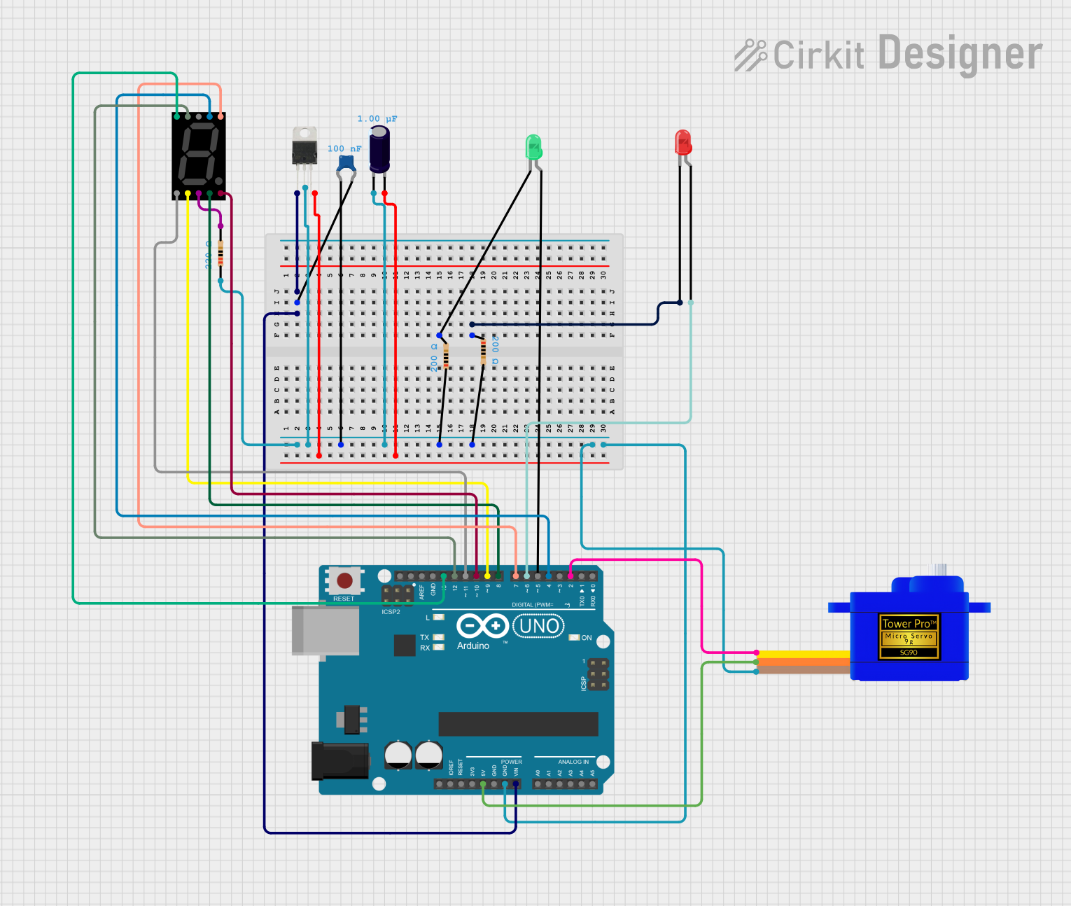


Explore Projects Built with 7 semi vikram 10a
Common Applications
- Large LED-based 7-segment displays (e.g., outdoor signage, scoreboards)
- Industrial control panels
- Digital clocks and timers
- Voltage, current, or temperature display units
- Automotive dashboard displays
Technical Specifications
Key Technical Details
- Operating Voltage: 5V to 24V DC
- Maximum Current Handling: 10A (total across all segments)
- Input Logic Levels: Compatible with 3.3V and 5V logic
- Output Type: Open-drain outputs for each segment
- Segment Control: Supports common anode and common cathode configurations
- Thermal Protection: Built-in over-temperature shutdown
- Package Type: DIP-16 or SMD-16
- Operating Temperature Range: -40°C to 85°C
Pin Configuration and Descriptions
The Vikram 10A has 16 pins, as detailed in the table below:
| Pin Number | Pin Name | Description |
|---|---|---|
| 1 | VCC | Power supply input (5V to 24V DC). |
| 2 | GND | Ground connection. |
| 3 | SEG_A | Output for segment A of the 7-segment display. |
| 4 | SEG_B | Output for segment B of the 7-segment display. |
| 5 | SEG_C | Output for segment C of the 7-segment display. |
| 6 | SEG_D | Output for segment D of the 7-segment display. |
| 7 | SEG_E | Output for segment E of the 7-segment display. |
| 8 | SEG_F | Output for segment F of the 7-segment display. |
| 9 | SEG_G | Output for segment G of the 7-segment display. |
| 10 | SEG_DP | Output for the decimal point (DP) of the display. |
| 11 | ENABLE | Enable pin for the driver (active HIGH). |
| 12 | MODE | Selects common anode (HIGH) or common cathode (LOW) configuration. |
| 13 | DATA_IN | Serial data input for controlling the segments. |
| 14 | CLK | Clock input for serial data communication. |
| 15 | LATCH | Latch input to update the display with new data. |
| 16 | NC | No connection (reserved for future use). |
Usage Instructions
How to Use the Vikram 10A in a Circuit
- Power Supply: Connect the VCC pin to a DC power source (5V to 24V) and the GND pin to ground.
- Display Connection: Connect the segment outputs (SEG_A to SEG_DP) to the corresponding segments of the 7-segment display. Ensure the display's common pin is connected to the appropriate voltage level based on the MODE pin setting.
- Control Signals: Use a microcontroller or other logic circuit to provide signals to the DATA_IN, CLK, and LATCH pins. These signals control which segments are lit.
- Enable the Driver: Set the ENABLE pin HIGH to activate the driver. If the pin is LOW, the driver will be disabled, and all outputs will be off.
- Mode Selection: Set the MODE pin HIGH for common anode displays or LOW for common cathode displays.
Important Considerations and Best Practices
- Current Limiting: Use appropriate resistors or current-limiting circuitry to prevent overdriving the LED segments.
- Thermal Management: Ensure adequate ventilation or heat sinking if operating near the maximum current rating.
- Signal Timing: Follow the timing requirements for DATA_IN, CLK, and LATCH signals as specified in the datasheet.
- Decoupling Capacitors: Place a 0.1µF ceramic capacitor close to the VCC and GND pins to reduce noise and improve stability.
Example: Interfacing with Arduino UNO
Below is an example code snippet for controlling the Vikram 10A with an Arduino UNO:
// Pin definitions for Arduino
#define DATA_IN 8  // Connect to Vikram 10A DATA_IN pin
#define CLK 9      // Connect to Vikram 10A CLK pin
#define LATCH 10   // Connect to Vikram 10A LATCH pin
#define ENABLE 11  // Connect to Vikram 10A ENABLE pin

void setup() {
  // Set pin modes
  pinMode(DATA_IN, OUTPUT);
  pinMode(CLK, OUTPUT);
  pinMode(LATCH, OUTPUT);
  pinMode(ENABLE, OUTPUT);

  // Enable the driver
  digitalWrite(ENABLE, HIGH);
}

void loop() {
  // Example: Display the number "8" on the 7-segment display
  byte segments = 0b11111111; // Binary representation for all segments ON

  // Send data to the Vikram 10A
  digitalWrite(LATCH, LOW); // Begin data transfer
  shiftOut(DATA_IN, CLK, MSBFIRST, segments); // Send segment data
  digitalWrite(LATCH, HIGH); // Latch data to update display

  delay(1000); // Wait for 1 second
}
Troubleshooting and FAQs
Common Issues and Solutions
Display Not Lighting Up:
- Ensure the ENABLE pin is set HIGH.
- Verify the power supply voltage and connections to the VCC and GND pins.
- Check the MODE pin configuration (common anode vs. common cathode).
Incorrect Segments Lighting:
- Verify the DATA_IN, CLK, and LATCH connections.
- Ensure the microcontroller is sending the correct segment data.
Overheating:
- Check for excessive current draw. Add current-limiting resistors if necessary.
- Ensure proper ventilation or heat sinking.
Flickering Display:
- Verify the timing of the CLK and LATCH signals.
- Add decoupling capacitors near the power pins to reduce noise.
FAQs
Q: Can the Vikram 10A drive multiple 7-segment displays?
A: Yes, but you will need to use multiplexing techniques or additional drivers to handle multiple displays.
Q: What happens if the current exceeds 10A?
A: The Vikram 10A includes thermal protection and will shut down to prevent damage. However, it is recommended to design the circuit to stay within the specified current limits.
Q: Is the Vikram 10A compatible with 3.3V microcontrollers?
A: Yes, the input logic levels are compatible with both 3.3V and 5V systems.