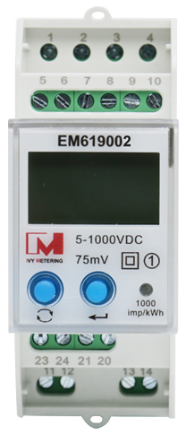
How to Use DC energy meter EM619002: Examples, Pinouts, and Specs
Introduction
The DC Energy Meter EM619002, manufactured by Ivy Metering, is a precision device designed to measure direct current (DC) energy consumption in electrical circuits. It provides real-time readings of voltage, current, and total energy usage over time, making it an essential tool for monitoring and managing energy efficiency in DC-powered systems.
Explore Projects Built with DC energy meter EM619002


Explore Projects Built with DC energy meter EM619002
Common Applications and Use Cases
- Solar power systems to monitor energy generation and consumption.
- Electric vehicle (EV) charging stations for tracking energy usage.
- Industrial DC systems for energy management and optimization.
- Battery monitoring in renewable energy storage systems.
- Laboratory and testing environments requiring precise DC energy measurements.
Technical Specifications
The following table outlines the key technical details of the EM619002:
| Parameter | Specification |
|---|---|
| Manufacturer | Ivy Metering |
| Part ID | EM619002 |
| Voltage Range | 0–1000 V DC |
| Current Range | 0–500 A DC (with external shunt) |
| Power Range | 0–500 kW |
| Energy Measurement | 0–999999.99 kWh |
| Accuracy | ±0.5% |
| Communication Protocol | RS485 (Modbus RTU) |
| Power Supply | 12–24 V DC |
| Operating Temperature | -25°C to +70°C |
| Dimensions | 96 mm x 96 mm x 65 mm |
| Mounting Type | Panel-mounted |
Pin Configuration and Descriptions
The EM619002 features a terminal block for wiring connections. Below is the pin configuration:
| Pin Number | Label | Description |
|---|---|---|
| 1 | V+ | Positive voltage input |
| 2 | V- | Negative voltage input |
| 3 | I+ | Positive current input (connect to shunt) |
| 4 | I- | Negative current input (connect to shunt) |
| 5 | RS485 A | RS485 communication line A |
| 6 | RS485 B | RS485 communication line B |
| 7 | GND | Ground connection for power supply |
| 8 | Vcc | Positive power supply input (12–24 V DC) |
Usage Instructions
How to Use the EM619002 in a Circuit
Power Supply Connection:
- Connect the
Vccpin to a 12–24 V DC power source. - Connect the
GNDpin to the ground of the power source.
- Connect the
Voltage Measurement:
- Connect the
V+andV-pins across the DC voltage source to measure the voltage.
- Connect the
Current Measurement:
- Use an external shunt resistor rated for the expected current range.
- Connect the
I+andI-pins across the shunt resistor.
Communication Setup:
- Use the
RS485 AandRS485 Bpins to connect the meter to a Modbus RTU-compatible device (e.g., a PLC or computer). - Configure the communication parameters (baud rate, parity, etc.) as per the system requirements.
- Use the
Mounting:
- Install the meter in a panel cutout of 92 mm x 92 mm.
- Secure it using the provided mounting brackets.
Important Considerations and Best Practices
- Ensure proper polarity when connecting voltage and current inputs to avoid damage.
- Use appropriately rated cables and shunt resistors for the expected voltage and current levels.
- Verify the RS485 communication settings (e.g., baud rate, slave ID) to ensure compatibility with the host system.
- Avoid exposing the meter to extreme temperatures or humidity beyond its operating range.
- Regularly calibrate the meter if required for high-precision applications.
Example: Connecting to an Arduino UNO
The EM619002 can be interfaced with an Arduino UNO using an RS485-to-TTL converter. Below is an example code snippet to read voltage data using the Modbus RTU protocol:
#include <ModbusMaster.h>

// Instantiate ModbusMaster object
ModbusMaster node;

// Define RS485 communication pins
#define RE_PIN 2  // Receiver Enable pin
#define DE_PIN 3  // Driver Enable pin

void preTransmission() {
  digitalWrite(RE_PIN, HIGH); // Enable RS485 transmitter
  digitalWrite(DE_PIN, HIGH);
}

void postTransmission() {
  digitalWrite(RE_PIN, LOW);  // Disable RS485 transmitter
  digitalWrite(DE_PIN, LOW);
}

void setup() {
  // Initialize serial communication
  Serial.begin(9600); // Serial monitor
  Serial1.begin(9600); // RS485 communication

  // Configure RS485 control pins
  pinMode(RE_PIN, OUTPUT);
  pinMode(DE_PIN, OUTPUT);
  digitalWrite(RE_PIN, LOW);
  digitalWrite(DE_PIN, LOW);

  // Attach Modbus communication functions
  node.begin(1, Serial1); // Slave ID 1
  node.preTransmission(preTransmission);
  node.postTransmission(postTransmission);
}

void loop() {
  uint8_t result;
  uint16_t data;

  // Read voltage register (example register address: 0x0000)
  result = node.readInputRegisters(0x0000, 1);

  if (result == node.ku8MBSuccess) {
    data = node.getResponseBuffer(0);
    float voltage = data / 10.0; // Convert to volts (example scaling factor)
    Serial.print("Voltage: ");
    Serial.print(voltage);
    Serial.println(" V");
  } else {
    Serial.println("Failed to read voltage!");
  }

  delay(1000); // Wait 1 second before next reading
}
Note: Replace the register address (0x0000) and scaling factor (/10.0) with the correct values based on the EM619002's Modbus register map.
Troubleshooting and FAQs
Common Issues and Solutions
No Display or Readings:
- Verify the power supply voltage (12–24 V DC) and connections to
VccandGND. - Check for loose or incorrect wiring.
- Verify the power supply voltage (12–24 V DC) and connections to
Incorrect Voltage or Current Readings:
- Ensure proper polarity of the
V+,V-,I+, andI-connections. - Verify the shunt resistor's rating and connections.
- Ensure proper polarity of the
Communication Failure:
- Confirm the RS485 wiring and termination resistors.
- Check the Modbus settings (baud rate, parity, slave ID) on both the meter and the host device.
Overload or Error Indication:
- Ensure the measured voltage and current are within the meter's specified range.
- Inspect for short circuits or excessive loads in the circuit.
FAQs
Q1: Can the EM619002 measure AC energy?
No, the EM619002 is specifically designed for DC energy measurement and cannot be used for AC systems.
Q2: What is the maximum cable length for RS485 communication?
The RS485 standard supports cable lengths up to 1200 meters, but this may vary depending on the baud rate and cable quality.
Q3: How often should the meter be calibrated?
For high-precision applications, calibration is recommended annually or as specified by the manufacturer.
Q4: Can the meter store historical energy data?
No, the EM619002 provides real-time measurements but does not have onboard data storage. Use an external data logger for historical data.
Q5: Is the meter waterproof?
No, the EM619002 is not waterproof and should be installed in a dry, indoor environment.