Cirkit Designer Logo
Cirkit Designer
Your all-in-one circuit design IDE
Home / 
Component Documentation

How to Use esp 32 wroom : Examples, Pinouts, and Specs

Image of esp 32 wroom
Cirkit Designer LogoDesign with esp 32 wroom in Cirkit Designer

Introduction

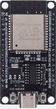
The ESP32 WROOM is a powerful microcontroller module with integrated Wi-Fi and Bluetooth capabilities, designed for Internet of Things (IoT) applications. It features a dual-core processor, ample GPIO pins, and supports various communication protocols, making it ideal for smart devices and embedded systems.

Explore Projects Built with esp 32 wroom

Use Cirkit Designer to design, explore, and prototype these projects online. Some projects support real-time simulation. Click "Open Project" to start designing instantly!
ESP32-Based Vibration Motor Controller with I2C IO Expansion
Image of VIBRATYION: A project utilizing esp 32 wroom  in a practical application
This circuit features an ESP32 Wroom Dev Kit microcontroller interfaced with an MCP23017 I/O expansion board via I2C communication, utilizing GPIO 21 and GPIO 22 for SDA and SCL lines, respectively. A vibration motor is controlled by an NPN transistor acting as a switch, with a diode for back EMF protection and a resistor to limit base current. The ESP32 can control the motor by sending signals to the MCP23017, which then interfaces with the transistor to turn the motor on or off.
Cirkit Designer LogoOpen Project in Cirkit Designer
ESP32-Based GPS Tracker with SD Card Logging and Barometric Sensor
Image of gps projekt circuit: A project utilizing esp 32 wroom  in a practical application
This circuit features an ESP32 Wroom Dev Kit as the main microcontroller, interfaced with an MPL3115A2 sensor for pressure and temperature readings, and a Neo 6M GPS module for location tracking. The ESP32 is also connected to an SD card reader for data logging purposes. A voltage regulator is used to step down the USB power supply to 3.3V, which powers the ESP32, the sensor, and the SD card reader.
Cirkit Designer LogoOpen Project in Cirkit Designer
ESP32-Based Multi-Sensor Health Monitoring System with Bluetooth Connectivity
Image of circuit diagram: A project utilizing esp 32 wroom  in a practical application
This circuit features an ESP32-WROOM-32UE microcontroller as the central processing unit, interfacing with a variety of sensors and modules. It includes a MAX30100 pulse oximeter and heart-rate sensor, an MLX90614 infrared thermometer, an HC-05 Bluetooth module for wireless communication, and a Neo 6M GPS module for location tracking. All components are powered by a common voltage supply and are connected to specific GPIO pins on the ESP32 for data exchange, with the sensors using I2C communication and the modules using UART.
Cirkit Designer LogoOpen Project in Cirkit Designer
Raspberry Pi Pico and ESP32 Wi-Fi Controlled Sensor Interface
Image of pico_esp32: A project utilizing esp 32 wroom  in a practical application
This circuit integrates a Raspberry Pi Pico and an ESP32 Wroom Dev Kit, interconnected through various GPIO pins and resistors, to enable communication and control between the two microcontrollers. The ESP32 is powered by a 3.3V supply and shares ground with the Raspberry Pi Pico, while specific GPIO pins are used for data exchange. The provided code sketches for the Raspberry Pi Pico suggest a framework for further development of the system's functionality.
Cirkit Designer LogoOpen Project in Cirkit Designer

Explore Projects Built with esp 32 wroom

Use Cirkit Designer to design, explore, and prototype these projects online. Some projects support real-time simulation. Click "Open Project" to start designing instantly!
Image of VIBRATYION: A project utilizing esp 32 wroom  in a practical application
ESP32-Based Vibration Motor Controller with I2C IO Expansion
This circuit features an ESP32 Wroom Dev Kit microcontroller interfaced with an MCP23017 I/O expansion board via I2C communication, utilizing GPIO 21 and GPIO 22 for SDA and SCL lines, respectively. A vibration motor is controlled by an NPN transistor acting as a switch, with a diode for back EMF protection and a resistor to limit base current. The ESP32 can control the motor by sending signals to the MCP23017, which then interfaces with the transistor to turn the motor on or off.
Cirkit Designer LogoOpen Project in Cirkit Designer
Image of gps projekt circuit: A project utilizing esp 32 wroom  in a practical application
ESP32-Based GPS Tracker with SD Card Logging and Barometric Sensor
This circuit features an ESP32 Wroom Dev Kit as the main microcontroller, interfaced with an MPL3115A2 sensor for pressure and temperature readings, and a Neo 6M GPS module for location tracking. The ESP32 is also connected to an SD card reader for data logging purposes. A voltage regulator is used to step down the USB power supply to 3.3V, which powers the ESP32, the sensor, and the SD card reader.
Cirkit Designer LogoOpen Project in Cirkit Designer
Image of circuit diagram: A project utilizing esp 32 wroom  in a practical application
ESP32-Based Multi-Sensor Health Monitoring System with Bluetooth Connectivity
This circuit features an ESP32-WROOM-32UE microcontroller as the central processing unit, interfacing with a variety of sensors and modules. It includes a MAX30100 pulse oximeter and heart-rate sensor, an MLX90614 infrared thermometer, an HC-05 Bluetooth module for wireless communication, and a Neo 6M GPS module for location tracking. All components are powered by a common voltage supply and are connected to specific GPIO pins on the ESP32 for data exchange, with the sensors using I2C communication and the modules using UART.
Cirkit Designer LogoOpen Project in Cirkit Designer
Image of pico_esp32: A project utilizing esp 32 wroom  in a practical application
Raspberry Pi Pico and ESP32 Wi-Fi Controlled Sensor Interface
This circuit integrates a Raspberry Pi Pico and an ESP32 Wroom Dev Kit, interconnected through various GPIO pins and resistors, to enable communication and control between the two microcontrollers. The ESP32 is powered by a 3.3V supply and shares ground with the Raspberry Pi Pico, while specific GPIO pins are used for data exchange. The provided code sketches for the Raspberry Pi Pico suggest a framework for further development of the system's functionality.
Cirkit Designer LogoOpen Project in Cirkit Designer

Common Applications and Use Cases

  • Smart home devices (e.g., smart lights, thermostats)
  • Wearable technology
  • Industrial IoT systems
  • Wireless sensor networks
  • Robotics and automation
  • Prototyping and development of connected devices

Technical Specifications

Key Technical Details

Specification Value
Microcontroller Tensilica Xtensa Dual-Core 32-bit LX6
Clock Speed Up to 240 MHz
Flash Memory 4 MB (varies by model)
SRAM 520 KB
Wi-Fi Standard 802.11 b/g/n
Bluetooth v4.2 BR/EDR and BLE
Operating Voltage 3.3V
Input Voltage Range 3.0V to 3.6V
GPIO Pins 34 (multipurpose)
Communication Protocols UART, SPI, I2C, I2S, CAN, PWM, ADC, DAC
ADC Resolution 12-bit
DAC Resolution 8-bit
Operating Temperature Range -40°C to 85°C
Power Consumption Ultra-low power modes available

Pin Configuration and Descriptions

The ESP32 WROOM module has 38 pins. Below is a summary of the key pins and their functions:

Pin Number Pin Name Function
1 EN Enable pin (active high)
2 IO0 GPIO0, used for boot mode selection
3 IO1 (TX0) GPIO1, UART0 TX
4 IO3 (RX0) GPIO3, UART0 RX
5 IO4 GPIO4, PWM, ADC, or other functions
6 IO5 GPIO5, PWM, ADC, or other functions
7 IO12 GPIO12, ADC2, touch sensor
8 IO13 GPIO13, ADC2, touch sensor
9 IO14 GPIO14, ADC2, touch sensor
10 IO15 GPIO15, ADC2, touch sensor
11 IO16 GPIO16, UART2 RX
12 IO17 GPIO17, UART2 TX
13 IO18 GPIO18, SPI CLK
14 IO19 GPIO19, SPI MISO
15 IO21 GPIO21, I2C SDA
16 IO22 GPIO22, I2C SCL
17 IO23 GPIO23, SPI MOSI
18 GND Ground
19 3V3 3.3V power supply

Note: Some GPIO pins have specific restrictions or are used during boot. Refer to the ESP32 datasheet for detailed pin behavior.

Usage Instructions

How to Use the ESP32 WROOM in a Circuit

  1. Power Supply: Ensure the module is powered with a stable 3.3V supply. Avoid exceeding 3.6V to prevent damage.
  2. Boot Mode: To upload code, connect GPIO0 to GND during reset. For normal operation, leave GPIO0 unconnected or pull it high.
  3. Connections:
    • Use UART pins (TX0, RX0) for programming and serial communication.
    • Connect GPIO pins to peripherals like sensors, LEDs, or motors as needed.
  4. Programming: The ESP32 WROOM can be programmed using the Arduino IDE, ESP-IDF, or other compatible environments.

Important Considerations and Best Practices

  • Voltage Levels: Ensure all connected peripherals operate at 3.3V logic levels. Use level shifters if interfacing with 5V devices.
  • Wi-Fi Antenna: Avoid placing metal objects near the onboard antenna to maintain signal strength.
  • Power Consumption: Use deep sleep modes to reduce power consumption in battery-powered applications.
  • GPIO Restrictions: Some GPIO pins are used during boot and should not be pulled high or low at startup.

Example Code for Arduino UNO

Below is an example of how to blink an LED connected to GPIO2 of the ESP32 WROOM using the Arduino IDE:

// Define the GPIO pin for the LED
#define LED_PIN 2

void setup() {
  // Initialize the LED pin as an output
  pinMode(LED_PIN, OUTPUT);
}

void loop() {
  // Turn the LED on
  digitalWrite(LED_PIN, HIGH);
  delay(1000); // Wait for 1 second

  // Turn the LED off
  digitalWrite(LED_PIN, LOW);
  delay(1000); // Wait for 1 second
}

Note: Ensure the ESP32 board is selected in the Arduino IDE under Tools > Board.

Troubleshooting and FAQs

Common Issues and Solutions

  1. ESP32 Not Detected by Computer:

    • Ensure the correct USB driver is installed (e.g., CP210x or CH340 driver).
    • Check the USB cable for data transfer capability (some cables are power-only).
  2. Code Upload Fails:

    • Verify that GPIO0 is connected to GND during reset for bootloader mode.
    • Check the selected COM port and board settings in the Arduino IDE.
  3. Wi-Fi Connection Issues:

    • Ensure the correct SSID and password are used in the code.
    • Check for interference or weak signal strength near the ESP32.
  4. Random Resets or Instability:

    • Verify the power supply provides sufficient current (at least 500mA).
    • Add decoupling capacitors near the power pins to stabilize voltage.

FAQs

Q: Can the ESP32 WROOM operate on 5V?
A: No, the ESP32 WROOM operates at 3.3V. Use a voltage regulator or level shifter for 5V systems.

Q: How do I use Bluetooth on the ESP32?
A: The ESP32 supports both Bluetooth Classic and BLE. Use the BluetoothSerial or BLE libraries in the Arduino IDE to implement Bluetooth functionality.

Q: What is the maximum Wi-Fi range of the ESP32?
A: The range depends on environmental factors but typically extends up to 50 meters indoors and 200 meters outdoors.

Q: Can I use the ESP32 WROOM for audio applications?
A: Yes, the ESP32 supports I2S for audio input/output and can be used for applications like streaming or audio processing.