Cirkit Designer Logo
Cirkit Designer
Your all-in-one circuit design IDE
Home / 
Component Documentation

How to Use Adafruit BNO055 STEMMA QT: Examples, Pinouts, and Specs

Image of Adafruit BNO055 STEMMA QT
Cirkit Designer LogoDesign with Adafruit BNO055 STEMMA QT in Cirkit Designer

Introduction

The Adafruit BNO055 STEMMA QT is a sophisticated sensor module that integrates three key sensors: an accelerometer, a gyroscope, and a magnetometer. This 9-DOF (degree of freedom) sensor is capable of providing precise orientation and motion tracking, making it an ideal choice for a wide range of applications, including robotics, navigation, human-machine interface, and gaming. Its ease of use and advanced features are well-suited for hobbyists, educators, and professionals alike.

Explore Projects Built with Adafruit BNO055 STEMMA QT

Use Cirkit Designer to design, explore, and prototype these projects online. Some projects support real-time simulation. Click "Open Project" to start designing instantly!
Arduino Nano and BNO055 Sensor with Bluetooth Connectivity
Image of Clutch Pedal Gyro: A project utilizing Adafruit BNO055 STEMMA QT in a practical application
This circuit features an Arduino Nano interfaced with a BNO055 sensor and an HC-05 Bluetooth module. The Arduino communicates with the BNO055 via I2C (using A4 for SDA and A5 for SCL) and with the HC-05 via serial communication (using D0/RX and D1/TX for data transfer). The HC-05's Key and State pins are connected to D2 and D3 of the Arduino for module control, and all components share a common ground with the Arduino powered at 5V and the BNO055 at 3.3V from the Arduino's 3V3 output.
Cirkit Designer LogoOpen Project in Cirkit Designer
Adafruit MPU6050 and VL6180X Sensor Interface with Servo Control
Image of wire: A project utilizing Adafruit BNO055 STEMMA QT in a practical application
This circuit features an Adafruit QT Py microcontroller interfaced with an Adafruit MPU6050 6-axis accelerometer/gyroscope and an Adafruit VL6180X Time of Flight (ToF) distance sensor, both connected via I2C communication. The QT Py also controls a Servomotor SG90, likely for physical actuation based on sensor inputs. The embedded code initializes the sensors, reads their data, and outputs the readings to a serial monitor, with the potential for motion control based on the sensor feedback.
Cirkit Designer LogoOpen Project in Cirkit Designer
Battery-Powered Smart Sensor Hub with Adafruit QT Py RP2040
Image of wearable final: A project utilizing Adafruit BNO055 STEMMA QT in a practical application
This circuit features an Adafruit QT Py RP2040 microcontroller interfaced with an APDS9960 proximity sensor, an MPU6050 accelerometer and gyroscope, and an OLED display via I2C communication. It also includes a buzzer controlled by the microcontroller and is powered by a 3.7V LiPo battery with a toggle switch for power control.
Cirkit Designer LogoOpen Project in Cirkit Designer
Battery-Powered Smart Light with Proximity Sensor and OLED Display using Adafruit QT Py RP2040
Image of lab: A project utilizing Adafruit BNO055 STEMMA QT in a practical application
This circuit is a portable, battery-powered system featuring an Adafruit QT Py RP2040 microcontroller that interfaces with an OLED display, a proximity sensor, an accelerometer, and an RGB LED strip. The system is powered by a lithium-ion battery with a step-up boost converter to provide 5V for the LED strip, and it includes a toggle switch for power control. The microcontroller communicates with the sensors and display via I2C.
Cirkit Designer LogoOpen Project in Cirkit Designer

Explore Projects Built with Adafruit BNO055 STEMMA QT

Use Cirkit Designer to design, explore, and prototype these projects online. Some projects support real-time simulation. Click "Open Project" to start designing instantly!
Image of Clutch Pedal Gyro: A project utilizing Adafruit BNO055 STEMMA QT in a practical application
Arduino Nano and BNO055 Sensor with Bluetooth Connectivity
This circuit features an Arduino Nano interfaced with a BNO055 sensor and an HC-05 Bluetooth module. The Arduino communicates with the BNO055 via I2C (using A4 for SDA and A5 for SCL) and with the HC-05 via serial communication (using D0/RX and D1/TX for data transfer). The HC-05's Key and State pins are connected to D2 and D3 of the Arduino for module control, and all components share a common ground with the Arduino powered at 5V and the BNO055 at 3.3V from the Arduino's 3V3 output.
Cirkit Designer LogoOpen Project in Cirkit Designer
Image of wire: A project utilizing Adafruit BNO055 STEMMA QT in a practical application
Adafruit MPU6050 and VL6180X Sensor Interface with Servo Control
This circuit features an Adafruit QT Py microcontroller interfaced with an Adafruit MPU6050 6-axis accelerometer/gyroscope and an Adafruit VL6180X Time of Flight (ToF) distance sensor, both connected via I2C communication. The QT Py also controls a Servomotor SG90, likely for physical actuation based on sensor inputs. The embedded code initializes the sensors, reads their data, and outputs the readings to a serial monitor, with the potential for motion control based on the sensor feedback.
Cirkit Designer LogoOpen Project in Cirkit Designer
Image of wearable final: A project utilizing Adafruit BNO055 STEMMA QT in a practical application
Battery-Powered Smart Sensor Hub with Adafruit QT Py RP2040
This circuit features an Adafruit QT Py RP2040 microcontroller interfaced with an APDS9960 proximity sensor, an MPU6050 accelerometer and gyroscope, and an OLED display via I2C communication. It also includes a buzzer controlled by the microcontroller and is powered by a 3.7V LiPo battery with a toggle switch for power control.
Cirkit Designer LogoOpen Project in Cirkit Designer
Image of lab: A project utilizing Adafruit BNO055 STEMMA QT in a practical application
Battery-Powered Smart Light with Proximity Sensor and OLED Display using Adafruit QT Py RP2040
This circuit is a portable, battery-powered system featuring an Adafruit QT Py RP2040 microcontroller that interfaces with an OLED display, a proximity sensor, an accelerometer, and an RGB LED strip. The system is powered by a lithium-ion battery with a step-up boost converter to provide 5V for the LED strip, and it includes a toggle switch for power control. The microcontroller communicates with the sensors and display via I2C.
Cirkit Designer LogoOpen Project in Cirkit Designer

Common Applications and Use Cases

  • Inertial Measurement Unit (IMU) for robotics
  • Orientation tracking for virtual reality (VR) and augmented reality (AR)
  • Motion detection for gaming controllers
  • Navigation systems for drones and unmanned vehicles
  • Fitness and health monitoring devices

Technical Specifications

Key Technical Details

  • Operating Voltage: 3.3V to 5V
  • Interface: I2C (up to 400kHz) and UART
  • Operating Temperature Range: -40°C to +85°C
  • Output Data Rate: Configurable from 1Hz to 100Hz

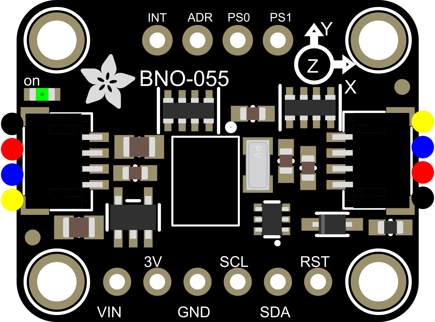
Pin Configuration and Descriptions

Pin Number Name Description
1 VIN Power supply (3.3V to 5V)
2 GND Ground connection
3 SCL I2C clock line
4 SDA I2C data line
5 PS0 Protocol select (pull to GND for I2C)
6 PS1 Not connected (NC)
7 RST Reset input (active low)
8 INT Interrupt output (active low)

Usage Instructions

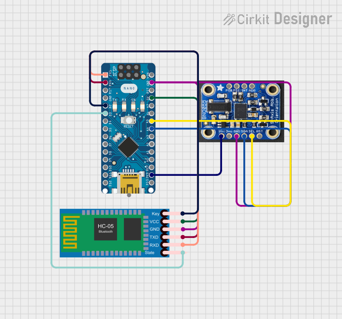
How to Use the Component in a Circuit

  1. Powering the Sensor: Connect the VIN pin to a 3.3V or 5V power supply, and the GND pin to the ground.
  2. I2C Communication: Connect the SCL and SDA pins to the I2C clock and data lines on your microcontroller. Ensure pull-up resistors are in place if not provided by the microcontroller board.
  3. Reset and Interrupts: Optionally, connect the RST pin to a digital output on your microcontroller to control the reset function, and the INT pin to an interrupt-capable digital input to handle interrupts from the sensor.
  4. Protocol Selection: For I2C communication, ensure the PS0 pin is connected to GND.

Important Considerations and Best Practices

  • Always ensure that the power supply voltage is within the specified range to prevent damage to the sensor.
  • Use proper decoupling capacitors close to the sensor's power supply pin to minimize power supply noise.
  • When using I2C, be aware of the bus speed limitations and address conflicts with other I2C devices.
  • For optimal performance, calibrate the magnetometer in the application's environment to account for any magnetic distortions.

Example Code for Arduino UNO

#include <Wire.h>
#include <Adafruit_Sensor.h>
#include <Adafruit_BNO055.h>

// Check the I2C address in the datasheet and update if necessary
#define BNO055_ADDRESS (0x28)

Adafruit_BNO055 bno = Adafruit_BNO055(55, BNO055_ADDRESS);

void setup() {
  Serial.begin(9600);
  if (!bno.begin()) {
    // There was a problem detecting the BNO055, check connections
    Serial.println("No BNO055 detected. Check wiring!");
    while (1);
  }
  delay(1000);
  bno.setExtCrystalUse(true);
}

void loop() {
  // Get a new sensor event
  sensors_event_t event;
  bno.getEvent(&event);

  // Display the orientation data
  Serial.print("Orientation: ");
  Serial.print("X: ");
  Serial.print(event.orientation.x, 4);
  Serial.print(" Y: ");
  Serial.print(event.orientation.y, 4);
  Serial.print(" Z: ");
  Serial.print(event.orientation.z, 4);
  Serial.println("");

  delay(100); // Adjust to the desired output data rate
}

Troubleshooting and FAQs

Common Issues Users Might Face

  • Sensor Not Detected: Ensure that the wiring is correct, and the power supply is within the specified range. Check the I2C address used in the code matches the sensor's address.
  • Inaccurate Readings: Perform sensor calibration, especially for the magnetometer, to improve accuracy. Ensure the sensor is placed away from magnetic fields and metals that can distort readings.
  • Intermittent Communication: Check for loose connections and ensure that the I2C bus is not overloaded with too many devices or long cable runs.

Solutions and Tips for Troubleshooting

  • Power Cycling: Sometimes simply resetting the power to the sensor can resolve communication issues.
  • I2C Pull-up Resistors: Verify that appropriate pull-up resistors are in place for the I2C lines, typically 4.7kΩ to 10kΩ.
  • Code Debugging: Use serial print statements to debug and verify that the microcontroller is running the code correctly and communicating with the sensor.

FAQs

Q: Can the BNO055 be used with a 5V microcontroller like the Arduino UNO? A: Yes, the BNO055 STEMMA QT can be interfaced with a 5V microcontroller as it is 5V tolerant on the I2C pins.

Q: How do I calibrate the BNO055? A: Calibration involves moving the sensor in specific patterns. Adafruit provides a calibration guide and example code to assist with this process.

Q: What is the purpose of the INT pin? A: The INT pin can be used to receive interrupt signals from the BNO055, such as when new sensor data is available or when certain motion thresholds are exceeded.

Q: How can I change the output data rate? A: The output data rate can be configured using the BNO055's internal registers. Adafruit's BNO055 library provides functions to adjust these settings easily.

For further assistance, consult the Adafruit BNO055 STEMMA QT datasheet and the Adafruit support forums.