Cirkit Designer Logo
Cirkit Designer
Your all-in-one circuit design IDE
Home / 
Component Documentation

How to Use Adafruit Mini 8x8 LED Matrix Backpack - Yellow: Examples, Pinouts, and Specs
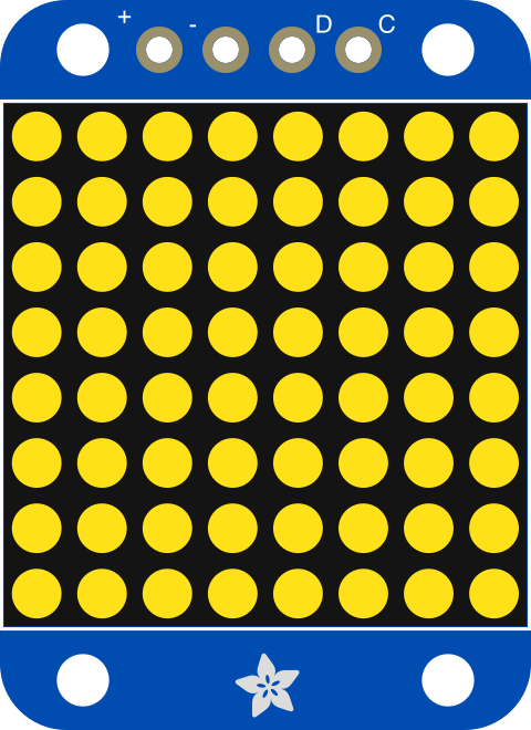

Image of Adafruit Mini 8x8 LED Matrix Backpack - Yellow
Cirkit Designer LogoDesign with Adafruit Mini 8x8 LED Matrix Backpack - Yellow in Cirkit Designer

Introduction

The Adafruit Mini 8x8 LED Matrix Backpack (Part ID: 871) is a compact and versatile LED display module featuring an 8x8 grid of yellow LEDs. This module is designed to simplify the process of adding visual output to your projects. It integrates seamlessly with microcontrollers, such as Arduino, and uses the I2C communication protocol for easy control. The backpack design minimizes wiring complexity, making it ideal for prototyping and compact designs.

Explore Projects Built with Adafruit Mini 8x8 LED Matrix Backpack - Yellow
Use Cirkit Designer to design, explore, and prototype these projects online. Some projects support real-time simulation. Click "Open Project" to start designing instantly!
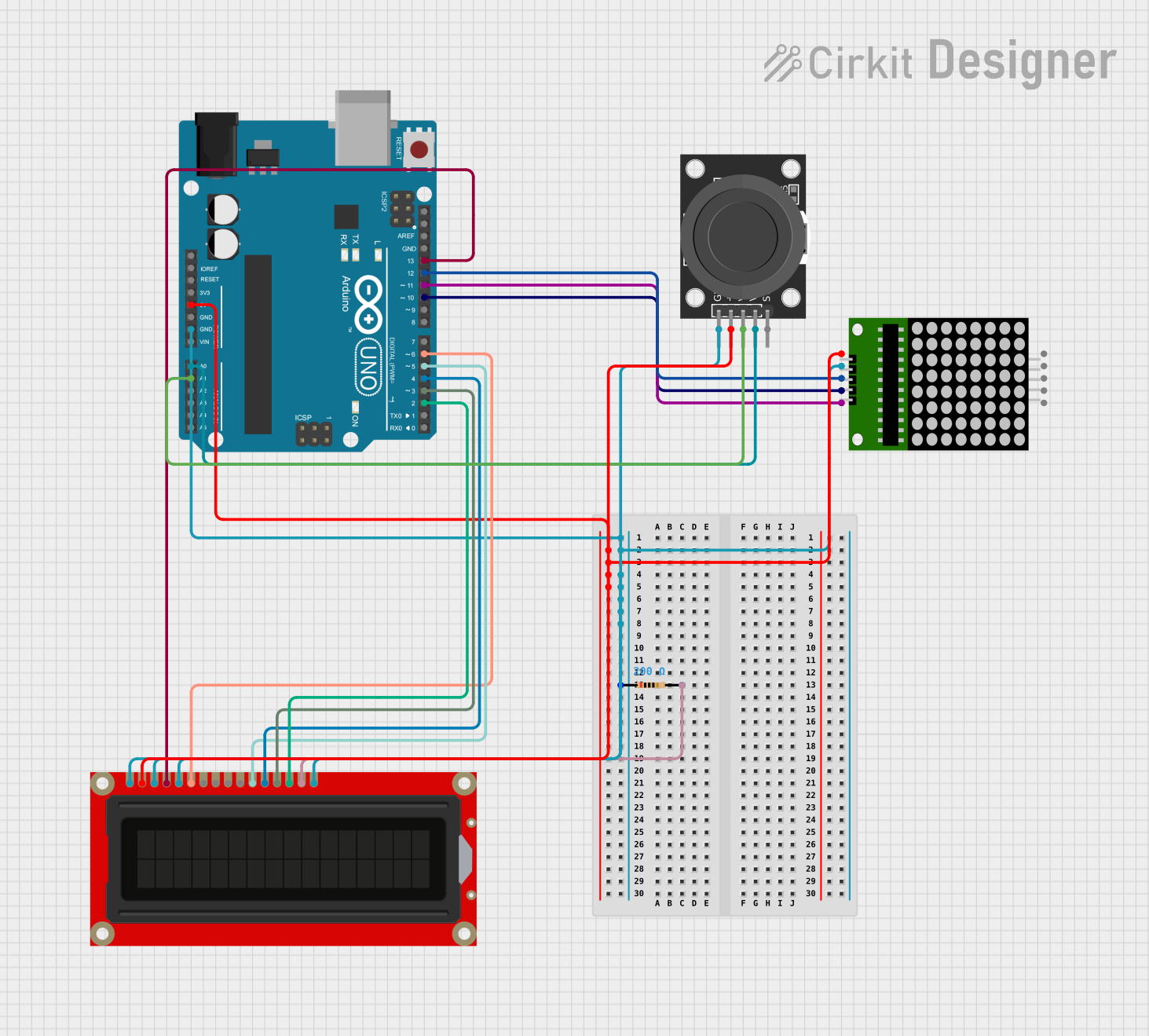
Arduino UNO Controlled LED Matrix and LCD Interface with Joystick Interaction
Image of Digital Game Circuit: A project utilizing Adafruit Mini 8x8 LED Matrix Backpack - Yellow in a practical application
This circuit features an Arduino UNO microcontroller interfaced with an 8x8 LED matrix, an LCD screen, and a KY-023 Dual Axis Joystick Module. The Arduino controls the LED matrix via digital pins D10-D12 and powers the matrix, LCD, and joystick module from its 5V output. The joystick's analog outputs are connected to the Arduino's analog inputs A0 and A1 for position sensing, while the LCD is controlled through digital pins D2-D6 and D13 for display purposes.
Cirkit Designer LogoOpen Project in Cirkit Designer
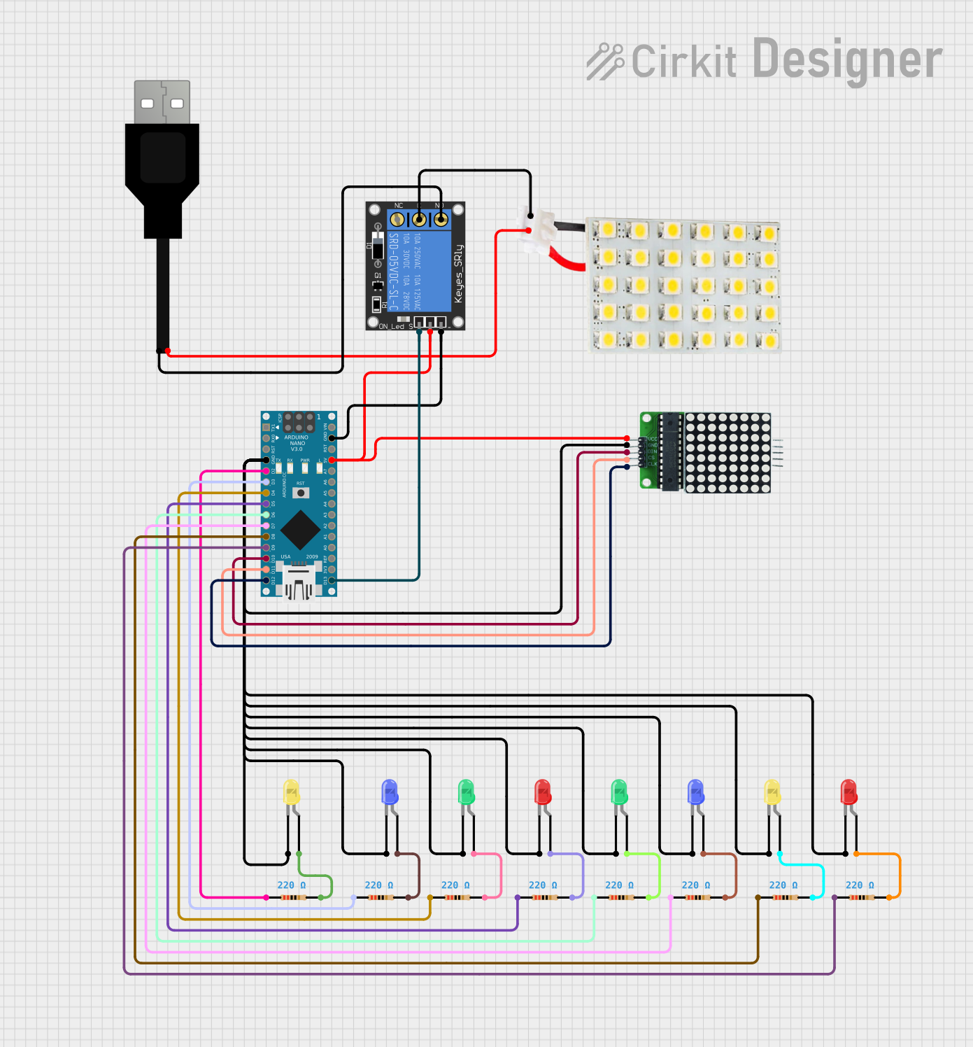
Arduino Nano Controlled LED Display and Relay System
Image of Design for Arduino Nano: A project utilizing Adafruit Mini 8x8 LED Matrix Backpack - Yellow in a practical application
This circuit features an Arduino Nano microcontroller connected to an 8x8 LED matrix and multiple individual LEDs with current-limiting resistors. The Arduino controls the LED matrix and individual LEDs, likely for display or signaling purposes. Additionally, there is a 1-channel relay module that can be controlled by the Arduino to switch external loads, and a USB connection for power and potential programming of the Arduino.
Cirkit Designer LogoOpen Project in Cirkit Designer
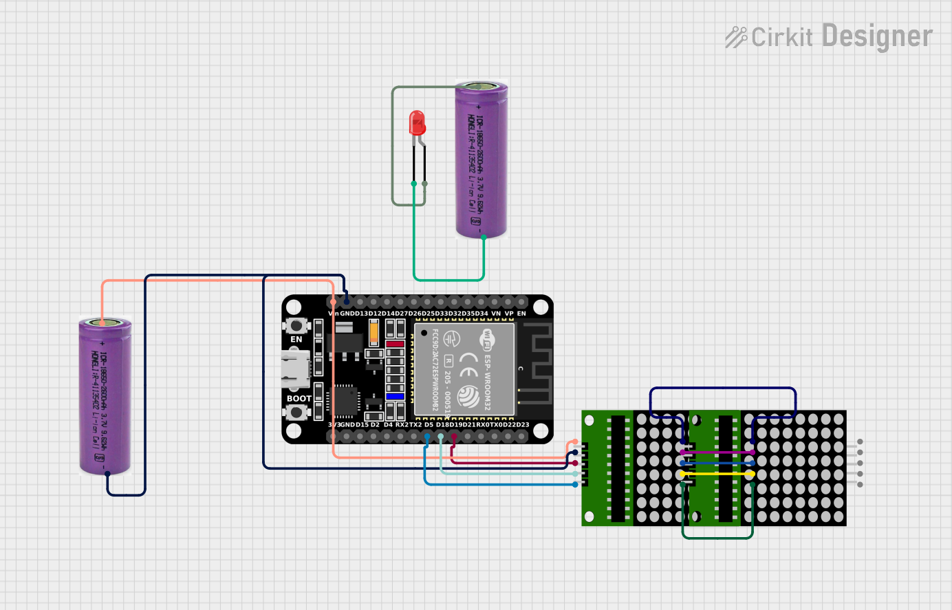
ESP32-Controlled Dual 8x8 LED Matrix Display with NTP Time Synchronization
Image of time: A project utilizing Adafruit Mini 8x8 LED Matrix Backpack - Yellow in a practical application
This circuit features an ESP32 microcontroller connected to two cascaded 8x8 LED matrix displays, powered by a 3.3V battery. The ESP32 drives the displays to show time and other information, with the code indicating functionality for connecting to WiFi, synchronizing time via NTP, and displaying data on the matrices using custom fonts. Additionally, there is a separate 3.3V battery powering a red LED, which appears to function as a simple indicator light.
Cirkit Designer LogoOpen Project in Cirkit Designer
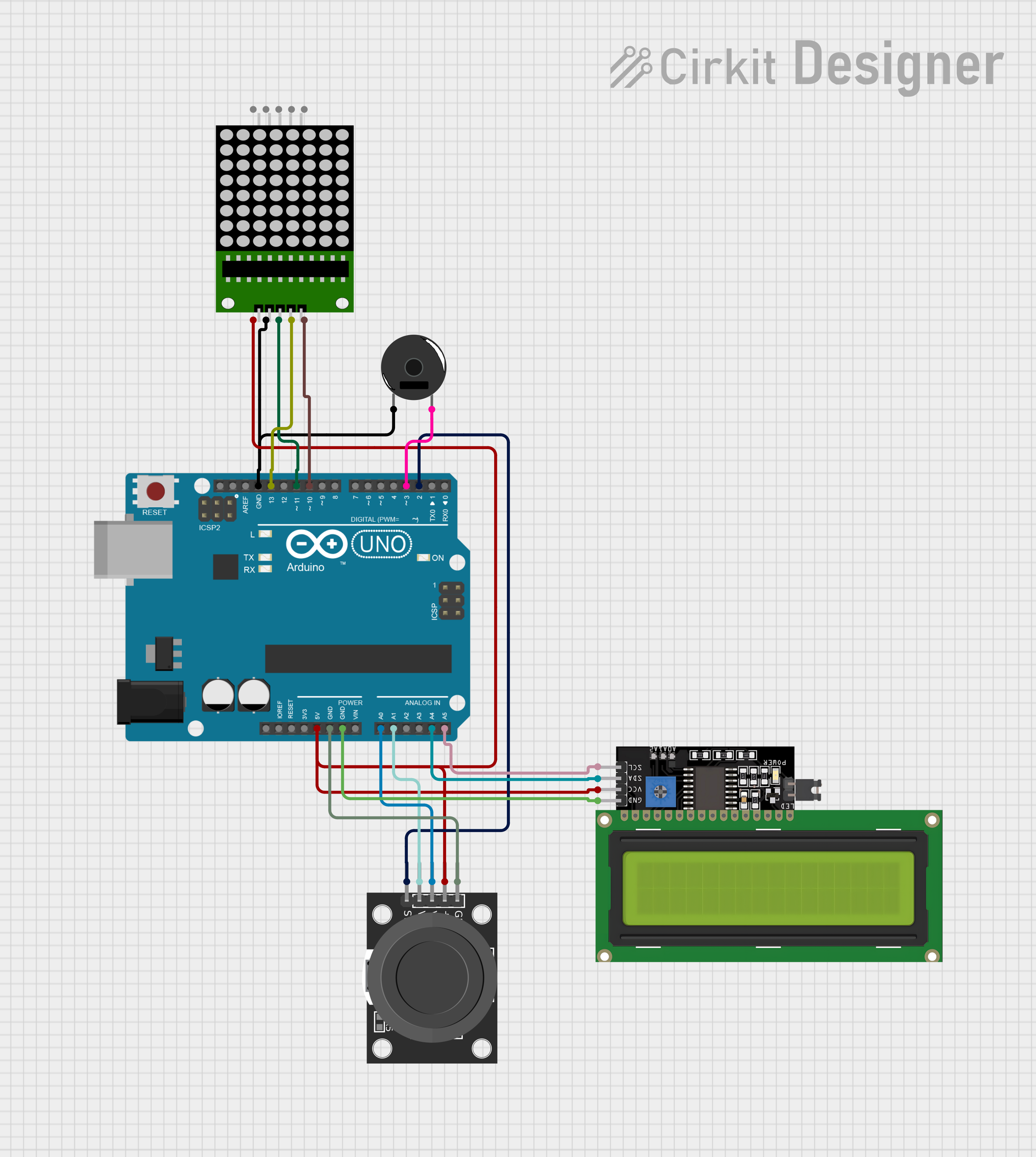
Arduino UNO Controlled Interactive Display with Joystick and Buzzer Feedback
Image of joystick: A project utilizing Adafruit Mini 8x8 LED Matrix Backpack - Yellow in a practical application
This circuit features an Arduino UNO microcontroller connected to an 8x8 LED matrix, an LCD display with I2C interface, a KY-023 Dual Axis Joystick Module, and a Piezo Buzzer. The Arduino controls the LED matrix via digital pins and provides an interface for the joystick's analog inputs and button press. The LCD display is used for output, and the buzzer is driven by a digital pin for audio feedback.
Cirkit Designer LogoOpen Project in Cirkit Designer

Explore Projects Built with Adafruit Mini 8x8 LED Matrix Backpack - Yellow

Use Cirkit Designer to design, explore, and prototype these projects online. Some projects support real-time simulation. Click "Open Project" to start designing instantly!
Image of Digital Game Circuit: A project utilizing Adafruit Mini 8x8 LED Matrix Backpack - Yellow in a practical application
Arduino UNO Controlled LED Matrix and LCD Interface with Joystick Interaction
This circuit features an Arduino UNO microcontroller interfaced with an 8x8 LED matrix, an LCD screen, and a KY-023 Dual Axis Joystick Module. The Arduino controls the LED matrix via digital pins D10-D12 and powers the matrix, LCD, and joystick module from its 5V output. The joystick's analog outputs are connected to the Arduino's analog inputs A0 and A1 for position sensing, while the LCD is controlled through digital pins D2-D6 and D13 for display purposes.
Cirkit Designer LogoOpen Project in Cirkit Designer
Image of Design for Arduino Nano: A project utilizing Adafruit Mini 8x8 LED Matrix Backpack - Yellow in a practical application
Arduino Nano Controlled LED Display and Relay System
This circuit features an Arduino Nano microcontroller connected to an 8x8 LED matrix and multiple individual LEDs with current-limiting resistors. The Arduino controls the LED matrix and individual LEDs, likely for display or signaling purposes. Additionally, there is a 1-channel relay module that can be controlled by the Arduino to switch external loads, and a USB connection for power and potential programming of the Arduino.
Cirkit Designer LogoOpen Project in Cirkit Designer
Image of time: A project utilizing Adafruit Mini 8x8 LED Matrix Backpack - Yellow in a practical application
ESP32-Controlled Dual 8x8 LED Matrix Display with NTP Time Synchronization
This circuit features an ESP32 microcontroller connected to two cascaded 8x8 LED matrix displays, powered by a 3.3V battery. The ESP32 drives the displays to show time and other information, with the code indicating functionality for connecting to WiFi, synchronizing time via NTP, and displaying data on the matrices using custom fonts. Additionally, there is a separate 3.3V battery powering a red LED, which appears to function as a simple indicator light.
Cirkit Designer LogoOpen Project in Cirkit Designer
Image of joystick: A project utilizing Adafruit Mini 8x8 LED Matrix Backpack - Yellow in a practical application
Arduino UNO Controlled Interactive Display with Joystick and Buzzer Feedback
This circuit features an Arduino UNO microcontroller connected to an 8x8 LED matrix, an LCD display with I2C interface, a KY-023 Dual Axis Joystick Module, and a Piezo Buzzer. The Arduino controls the LED matrix via digital pins and provides an interface for the joystick's analog inputs and button press. The LCD display is used for output, and the buzzer is driven by a digital pin for audio feedback.
Cirkit Designer LogoOpen Project in Cirkit Designer

Common Applications

  • Visual indicators for IoT devices
  • Scrolling text displays
  • Simple animations or icons
  • Status indicators for embedded systems
  • Educational projects and prototyping

Technical Specifications

Key Technical Details

Parameter Value
LED Matrix Dimensions 8x8 (64 LEDs total)
LED Color Yellow
Operating Voltage 5V DC
Communication Protocol I2C
Default I2C Address 0x70
Current Consumption ~20mA (varies with brightness)
Dimensions 27mm x 27mm x 4mm

Pin Configuration

The Adafruit Mini 8x8 LED Matrix Backpack has four pins for connection:

Pin Name Description
VIN Power supply input (3.3V to 5V DC)
GND Ground
SDA I2C data line
SCL I2C clock line

Usage Instructions

How to Use the Component in a Circuit

  1. Wiring the Module:

    • Connect the VIN pin to the 5V output of your microcontroller.
    • Connect the GND pin to the ground (GND) of your microcontroller.
    • Connect the SDA pin to the I2C data line (A4 on Arduino UNO).
    • Connect the SCL pin to the I2C clock line (A5 on Arduino UNO).
  2. Install Required Libraries:

    • Download and install the Adafruit GFX and Adafruit LED Backpack libraries from the Arduino Library Manager.
  3. Upload Example Code:

    • Use the example code provided below to test the module.

Example Code for Arduino UNO

#include <Wire.h>
#include <Adafruit_GFX.h>
#include <Adafruit_LEDBackpack.h>

// Create an instance of the LED matrix
Adafruit_8x8matrix matrix = Adafruit_8x8matrix();

void setup() {
  // Initialize the LED matrix
  matrix.begin(0x70); // Default I2C address is 0x70
  matrix.clear();     // Clear the display
  matrix.writeDisplay();
}

void loop() {
  // Display a simple pattern (a smiley face)
  static const uint8_t smiley[] = {
    0b00111100,
    0b01000010,
    0b10100101,
    0b10000001,
    0b10100101,
    0b10011001,
    0b01000010,
    0b00111100
  };

  // Write the pattern to the matrix
  for (uint8_t i = 0; i < 8; i++) {
    matrix.drawBitmap(0, 0, smiley, 8, 8, LED_ON);
  }

  matrix.writeDisplay(); // Update the display
  delay(1000);           // Wait for 1 second

  // Clear the display
  matrix.clear();
  matrix.writeDisplay();
  delay(1000);           // Wait for 1 second
}

Important Considerations and Best Practices

  • Ensure the I2C address (default: 0x70) does not conflict with other devices on the same bus.
  • Use appropriate pull-up resistors on the SDA and SCL lines if your microcontroller does not have internal pull-ups enabled.
  • Avoid exceeding the maximum operating voltage of 5V to prevent damage to the module.
  • For optimal brightness, ensure your power supply can provide sufficient current.

Troubleshooting and FAQs

Common Issues and Solutions

  1. The LED matrix does not light up:

    • Verify all connections are secure and correct.
    • Ensure the module is powered with 5V and the ground is properly connected.
    • Check that the I2C address in your code matches the module's address.
  2. The display shows incorrect or garbled patterns:

    • Confirm that the SDA and SCL lines are connected to the correct pins on your microcontroller.
    • Ensure no other I2C devices are causing address conflicts.
  3. Brightness is too low:

    • Check the power supply voltage and current capacity.
    • Adjust the brightness settings in your code if supported.
  4. The module is not detected by the microcontroller:

    • Use an I2C scanner sketch to verify the module's address.
    • Ensure the Adafruit GFX and LED Backpack libraries are correctly installed.

FAQs

Q: Can I use this module with a 3.3V microcontroller?
A: Yes, the module is compatible with 3.3V logic levels, but ensure the VIN pin receives at least 3.3V.

Q: How do I change the I2C address?
A: The I2C address can be changed by soldering the address jumpers on the back of the module. Refer to the Adafruit documentation for details.

Q: Can I daisy-chain multiple LED matrix modules?
A: Yes, you can connect multiple modules by assigning each a unique I2C address.

Q: Is it possible to display animations?
A: Yes, you can create animations by updating the display with different patterns in quick succession.

This concludes the documentation for the Adafruit Mini 8x8 LED Matrix Backpack - Yellow. For further assistance, refer to the official Adafruit guide or community forums.