How to Use DFRobot Audio Analyzer: Examples, Pinouts, and Specs
Introduction
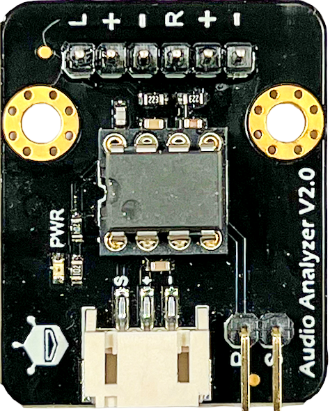
The DFRobot Audio Analyzer is a versatile device designed to analyze audio signals and provide detailed data on their characteristics, such as frequency, amplitude, and signal strength. This component is widely used in sound engineering, audio visualization, and educational projects. Its compact design and ease of integration make it an excellent choice for hobbyists, students, and professionals working on audio-related applications.
Explore Projects Built with DFRobot Audio Analyzer
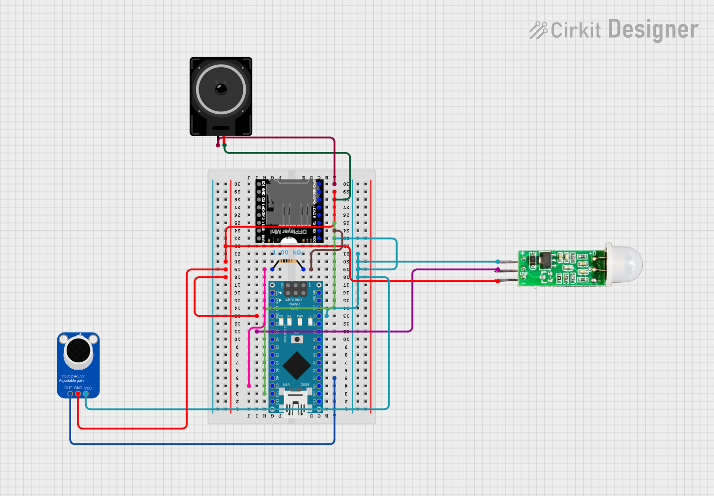
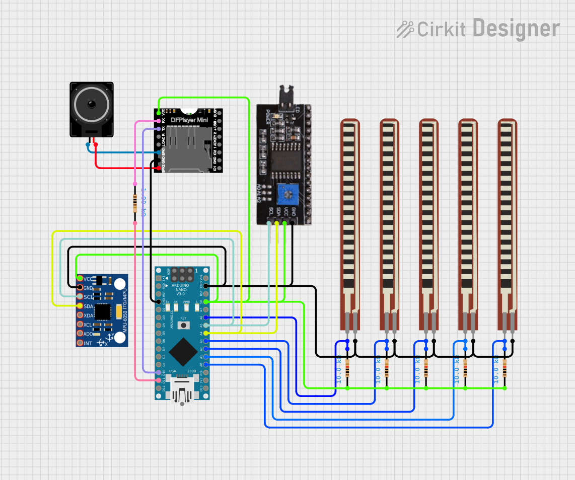
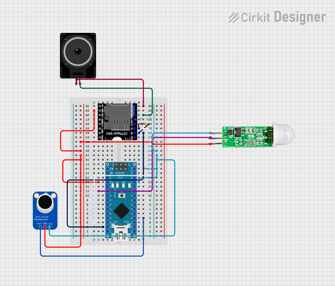
Explore Projects Built with DFRobot Audio Analyzer
Common Applications
- Audio spectrum analysis and visualization
- Sound engineering and signal processing
- Educational projects for learning audio signal behavior
- Real-time audio monitoring in embedded systems
- Integration with microcontrollers like Arduino for interactive projects
Technical Specifications
The DFRobot Audio Analyzer is equipped with advanced features to ensure accurate and reliable audio signal analysis. Below are its key technical specifications:
| Parameter | Specification |
|---|---|
| Operating Voltage | 3.3V to 5V DC |
| Operating Current | ≤ 20mA |
| Input Signal Range | 0.2V to 1.0V RMS |
| Frequency Range | 20Hz to 20kHz |
| Output Data Format | Analog and digital (via I2C) |
| Dimensions | 30mm x 22mm |
| Operating Temperature | -40°C to 85°C |
Pin Configuration
The DFRobot Audio Analyzer has a simple pin layout for easy integration into your projects. Below is the pin configuration:
| Pin | Name | Description |
|---|---|---|
| 1 | VCC | Power supply input (3.3V to 5V DC) |
| 2 | GND | Ground connection |
| 3 | AUDIO_IN | Audio signal input (connect to the audio source) |
| 4 | ANALOG_OUT | Analog output signal representing the amplitude of the audio input |
| 5 | SCL | I2C clock line for digital data communication |
| 6 | SDA | I2C data line for digital data communication |
Usage Instructions
How to Use the DFRobot Audio Analyzer in a Circuit
- Power the Module: Connect the
VCCpin to a 3.3V or 5V power source and theGNDpin to ground. - Connect the Audio Input: Feed the audio signal into the
AUDIO_INpin. Ensure the input signal is within the range of 0.2V to 1.0V RMS. - Read the Output:
- Use the
ANALOG_OUTpin to monitor the amplitude of the audio signal. - For more detailed analysis, connect the
SCLandSDApins to a microcontroller (e.g., Arduino) to retrieve digital data via I2C.
- Use the
Important Considerations
- Signal Conditioning: If the audio input signal exceeds the specified range, use a voltage divider or an attenuator circuit to prevent damage to the module.
- Noise Reduction: To minimize noise, use shielded cables for the audio input and keep the module away from high-frequency interference sources.
- I2C Address: The default I2C address of the module is
0x38. Ensure this address does not conflict with other devices on the I2C bus.
Example: Connecting to an Arduino UNO
Below is an example of how to use the DFRobot Audio Analyzer with an Arduino UNO to read audio data via I2C.
Circuit Diagram
- Connect
VCCto the 5V pin on the Arduino. - Connect
GNDto the GND pin on the Arduino. - Connect
SCLto the A5 pin on the Arduino (I2C clock line). - Connect
SDAto the A4 pin on the Arduino (I2C data line).
Arduino Code
#include <Wire.h> // Include the Wire library for I2C communication

#define AUDIO_ANALYZER_ADDR 0x38 // Default I2C address of the Audio Analyzer

void setup() {
  Wire.begin(); // Initialize I2C communication
  Serial.begin(9600); // Start serial communication for debugging
  Serial.println("DFRobot Audio Analyzer Initialized");
}

void loop() {
  Wire.beginTransmission(AUDIO_ANALYZER_ADDR); // Start communication with the module
  Wire.write(0x00); // Request data from the module
  Wire.endTransmission();

  Wire.requestFrom(AUDIO_ANALYZER_ADDR, 2); // Request 2 bytes of data
  if (Wire.available() == 2) {
    int highByte = Wire.read(); // Read the high byte
    int lowByte = Wire.read();  // Read the low byte
    int amplitude = (highByte << 8) | lowByte; // Combine the two bytes

    Serial.print("Audio Amplitude: ");
    Serial.println(amplitude); // Print the amplitude value
  }

  delay(100); // Wait for 100ms before the next reading
}
Best Practices
- Use decoupling capacitors near the power pins to stabilize the power supply.
- Avoid exposing the module to extreme temperatures or humidity to ensure long-term reliability.
- Regularly calibrate the module if used in precision applications.
Troubleshooting and FAQs
Common Issues and Solutions
No Output Signal:
- Ensure the
AUDIO_INsignal is within the specified range (0.2V to 1.0V RMS). - Verify that the module is powered correctly (check
VCCandGNDconnections).
- Ensure the
I2C Communication Failure:
- Check the wiring of the
SCLandSDApins. - Ensure the I2C address (
0x38) matches the address in your code. - Use pull-up resistors (4.7kΩ to 10kΩ) on the
SCLandSDAlines if necessary.
- Check the wiring of the
High Noise in Output:
- Use shielded cables for the audio input.
- Place the module away from high-frequency noise sources, such as motors or switching power supplies.
FAQs
Q: Can the module handle stereo audio signals?
A: No, the DFRobot Audio Analyzer is designed for mono audio signals. Use a mixer circuit to combine stereo signals into a single channel if needed.
Q: What is the maximum sampling rate of the module?
A: The module supports audio signals within the frequency range of 20Hz to 20kHz, which is sufficient for most audio applications.
Q: Can I use this module with a Raspberry Pi?
A: Yes, the module can be used with a Raspberry Pi via the I2C interface. Ensure proper configuration of the I2C pins on the Raspberry Pi.
Q: Is the module compatible with 3.3V systems?
A: Yes, the module operates at both 3.3V and 5V, making it compatible with a wide range of microcontrollers.
By following this documentation, you can effectively integrate the DFRobot Audio Analyzer into your projects and achieve accurate audio signal analysis.