How to Use Motor Driver and Power Distribution Board for Romi Chassis: Examples, Pinouts, and Specs
Introduction
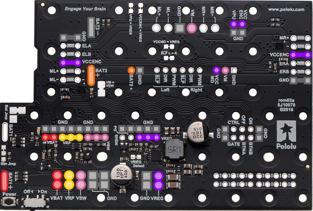
The Pololu Motor Driver and Power Distribution Board for Romi Chassis (Part ID: 3543) is a specialized circuit board designed to control the motors of the Romi chassis while efficiently distributing power to other components. This board integrates motor driver functionality with power management, making it an essential component for robotics projects using the Romi chassis. It simplifies the process of powering and controlling motors, sensors, and other peripherals, ensuring optimal performance and reliability.
Explore Projects Built with Motor Driver and Power Distribution Board for Romi Chassis


Explore Projects Built with Motor Driver and Power Distribution Board for Romi Chassis
Common Applications and Use Cases
- Robotics projects using the Pololu Romi chassis.
- Educational and hobbyist robotics platforms.
- Autonomous vehicles and small-scale robotic systems.
- Projects requiring efficient motor control and power distribution.
Technical Specifications
Key Technical Details
- Motor Driver: Dual-channel motor driver for independent control of two DC motors.
- Input Voltage Range: 6 V to 10 V.
- Continuous Motor Current: Up to 1.2 A per channel.
- Peak Motor Current: 1.5 A per channel.
- Logic Voltage: 3.3 V or 5 V (selectable).
- Power Distribution: Provides regulated 5 V and unregulated battery voltage to peripherals.
- Dimensions: 2.1" × 2.3" (53 mm × 58 mm).
- Weight: 13 g.
Pin Configuration and Descriptions
The board features multiple connectors for motor control, power input, and peripheral connections. Below is a detailed description of the key pins and connectors:
Motor Driver Pins
| Pin Name | Description |
|---|---|
| M1A, M1B | Motor 1 output terminals for connecting the first DC motor. |
| M2A, M2B | Motor 2 output terminals for connecting the second DC motor. |
| DIR1, DIR2 | Direction control inputs for Motor 1 and Motor 2. |
| PWM1, PWM2 | Pulse-width modulation (PWM) inputs for speed control of Motor 1 and 2. |
Power Input and Distribution
| Pin Name | Description |
|---|---|
| VIN | Main power input (6 V to 10 V). |
| GND | Ground connection. |
| 5V | Regulated 5 V output for powering peripherals. |
| VBAT | Unregulated battery voltage output for peripherals. |
Logic and Control Pins
| Pin Name | Description |
|---|---|
| VREG_EN | Enables the onboard 5 V regulator. |
| 3V3/5V_SEL | Selects the logic voltage level (3.3 V or 5 V). |
| GND | Ground connection for logic signals. |
Usage Instructions
How to Use the Component in a Circuit
Powering the Board:
- Connect a 6 V to 10 V power source to the
VINandGNDpins. - Ensure the power source can supply sufficient current for the motors and peripherals.
- Connect a 6 V to 10 V power source to the
Connecting Motors:
- Attach the first motor to the
M1AandM1Bterminals. - Attach the second motor to the
M2AandM2Bterminals.
- Attach the first motor to the
Logic Voltage Selection:
- Use the
3V3/5V_SELjumper to select the appropriate logic voltage level (3.3 V or 5 V) based on your microcontroller.
- Use the
Controlling the Motors:
- Use the
DIR1andDIR2pins to set the direction of Motor 1 and Motor 2, respectively. - Use the
PWM1andPWM2pins to control the speed of Motor 1 and Motor 2 using PWM signals.
- Use the
Powering Peripherals:
- Use the
5Vpin to power peripherals requiring regulated 5 V. - Use the
VBATpin to power peripherals requiring unregulated battery voltage.
- Use the
Important Considerations and Best Practices
- Ensure the total current draw of the motors and peripherals does not exceed the board's limits.
- Use appropriate heat dissipation methods if operating near the maximum current ratings.
- Verify the logic voltage level matches your microcontroller to avoid damage.
- Use decoupling capacitors on the power lines of sensitive peripherals to reduce noise.
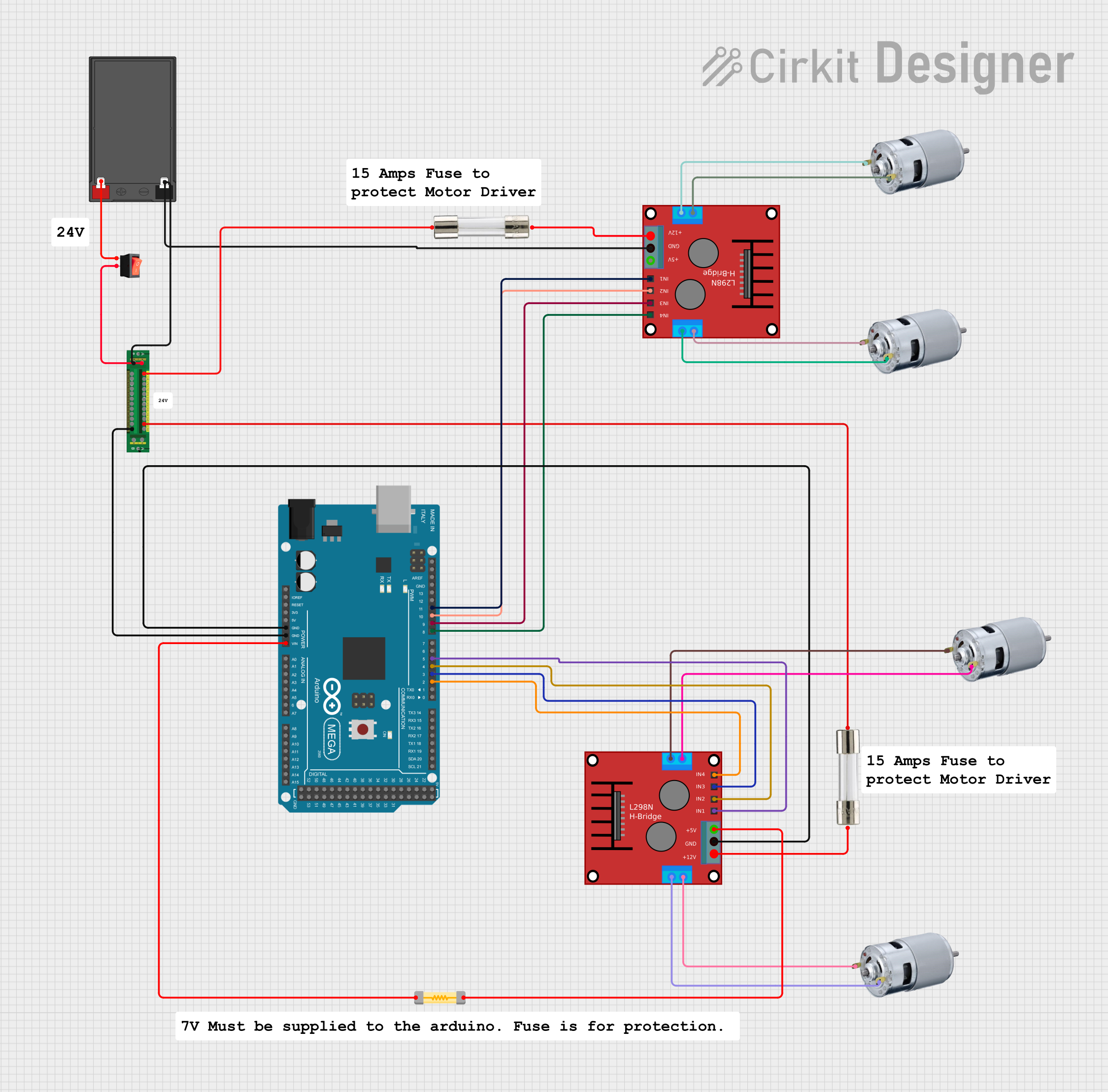
Example: Connecting to an Arduino UNO
Below is an example of how to control the motors using an Arduino UNO:
// Define motor control pins
const int DIR1 = 7;  // Direction pin for Motor 1
const int PWM1 = 6;  // PWM pin for Motor 1
const int DIR2 = 4;  // Direction pin for Motor 2
const int PWM2 = 5;  // PWM pin for Motor 2

void setup() {
  // Set motor control pins as outputs
  pinMode(DIR1, OUTPUT);
  pinMode(PWM1, OUTPUT);
  pinMode(DIR2, OUTPUT);
  pinMode(PWM2, OUTPUT);
}

void loop() {
  // Example: Drive Motor 1 forward at 50% speed
  digitalWrite(DIR1, HIGH);  // Set direction forward
  analogWrite(PWM1, 128);    // Set speed (0-255)

  // Example: Drive Motor 2 backward at 75% speed
  digitalWrite(DIR2, LOW);   // Set direction backward
  analogWrite(PWM2, 192);    // Set speed (0-255)

  delay(2000);  // Run motors for 2 seconds

  // Stop both motors
  analogWrite(PWM1, 0);
  analogWrite(PWM2, 0);

  delay(2000);  // Wait for 2 seconds
}
Troubleshooting and FAQs
Common Issues and Solutions
Motors Not Running:
- Verify the power source is connected and providing sufficient voltage and current.
- Check the motor connections to
M1A,M1B,M2A, andM2B. - Ensure the
DIRandPWMsignals are correctly configured.
Overheating:
- Ensure the motors are not drawing more current than the board's rated capacity.
- Use heat sinks or active cooling if operating near the maximum current limits.
Peripheral Devices Not Powering On:
- Check the
VREG_ENpin to ensure the 5 V regulator is enabled. - Verify the peripherals are connected to the correct power pins (
5VorVBAT).
- Check the
Logic Voltage Mismatch:
- Confirm the
3V3/5V_SELjumper is set to match your microcontroller's logic voltage.
- Confirm the
FAQs
Q: Can I use this board with a 12 V power source?
A: No, the maximum input voltage is 10 V. Using a higher voltage may damage the board.
Q: What type of motors can I use with this board?
A: The board is designed for brushed DC motors with a nominal voltage between 6 V and 10 V.
Q: Can I control the motors without a microcontroller?
A: Yes, you can use external switches or a manual PWM generator, but a microcontroller provides more precise control.
Q: Is this board compatible with other chassis?
A: While it is optimized for the Romi chassis, it can be used with other platforms that meet the voltage and current requirements.