How to Use MKE-M08 LCD2004 I2C Module: Examples, Pinouts, and Specs
Introduction
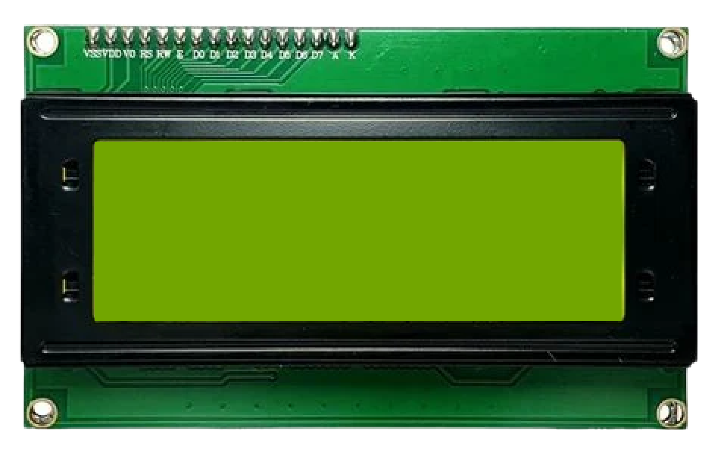
The MKE-M08 LCD2004 I2C Module is an electronic component designed to interface a standard 2004 character LCD display with a microcontroller through the I2C communication protocol. This module simplifies the process of connecting a 20x4 LCD as it requires only two data lines for communication, in addition to power and ground. It is widely used in DIY electronics, user interfaces, and display panels for showing textual information.
Explore Projects Built with MKE-M08 LCD2004 I2C Module
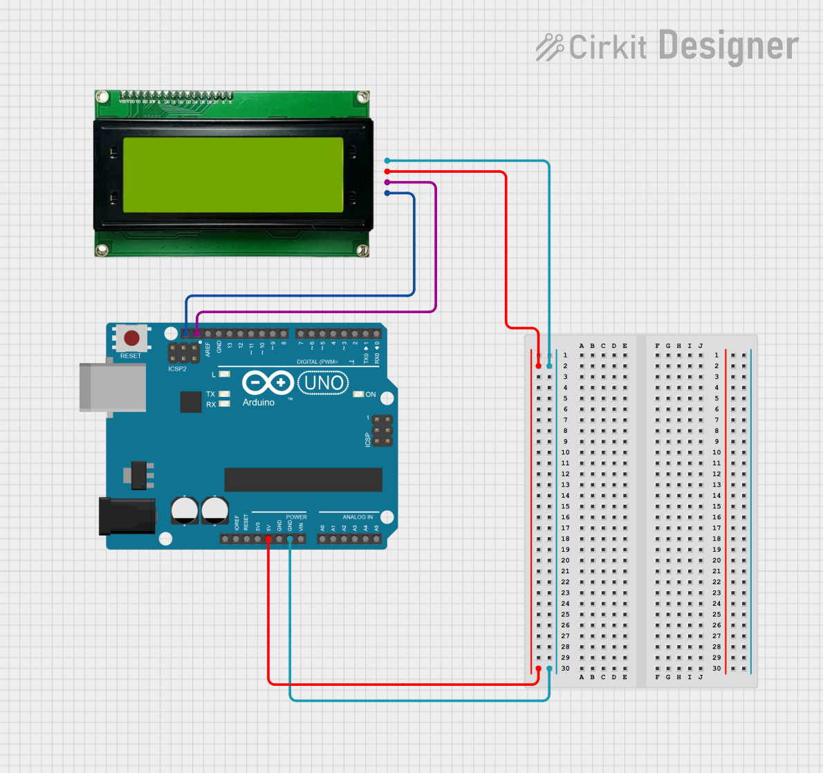
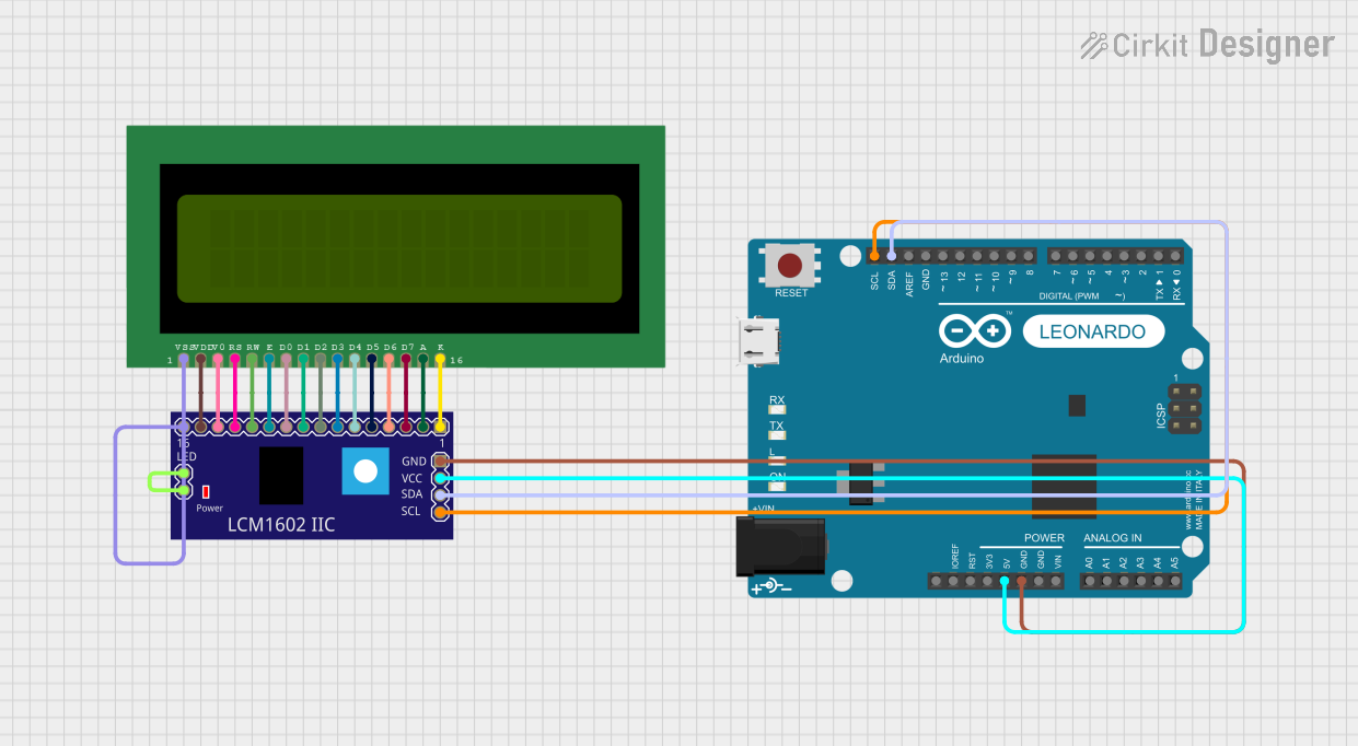

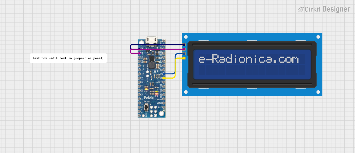
Explore Projects Built with MKE-M08 LCD2004 I2C Module
Common Applications and Use Cases
- Displaying sensor readings
- User interface for settings and menus
- Real-time clocks and timers
- Debugging information for development
Technical Specifications
Key Technical Details
- Operating Voltage: 5V
- I2C Address: 0x27 (default, can vary based on hardware)
- Backlight: Adjustable via software
- Display: 20 characters x 4 lines
Pin Configuration and Descriptions
| Pin | Function | Description |
|---|---|---|
| GND | Ground | Connect to system ground |
| VCC | Power Supply | Connect to 5V power source |
| SDA | I2C Data | Connect to I2C data line of microcontroller |
| SCL | I2C Clock | Connect to I2C clock line of microcontroller |
| NC | Not Connected | Not used in this module |
Usage Instructions
How to Use the Component in a Circuit
- Connect the GND pin to the ground of the power supply and microcontroller.
- Connect the VCC pin to a 5V power supply.
- Connect the SDA and SCL pins to the corresponding I2C data and clock lines on the microcontroller.
- If using an Arduino, ensure that pull-up resistors are present on the I2C lines. Most Arduino boards have built-in pull-up resistors.
Important Considerations and Best Practices
- Always power off the circuit before making any connections.
- Verify that the I2C address of the module does not conflict with other I2C devices on the same bus.
- Use the I2C scanner sketch to confirm the address of the module if unsure.
- Avoid long I2C cable runs to prevent signal degradation.
Example Code for Arduino UNO
#include <Wire.h>
#include <LiquidCrystal_I2C.h>

// Initialize the library with the I2C address 0x27 for the LCD
LiquidCrystal_I2C lcd(0x27, 20, 4);

void setup() {
  // Initialize the LCD and turn on the backlight
  lcd.init();
  lcd.backlight();

  // Print a message to the LCD
  lcd.setCursor(0, 0); // Set the cursor to the top-left position
  lcd.print("Hello, World!");
}

void loop() {
  // Main loop code (if required)
}
Troubleshooting and FAQs
Common Issues Users Might Face
- Display not powering on: Check connections to VCC and GND, and ensure the power supply is at 5V.
- Garbled or no text on display: Confirm that the I2C address is correct and that the SDA and SCL connections are secure.
- Backlight not working: Use the
lcd.backlight()function to turn on the backlight. If it still doesn't work, check the backlight circuitry on the module.
Solutions and Tips for Troubleshooting
- Use an I2C scanner sketch to verify the module's address.
- Check solder joints on the module for cold solder or bridges.
- Ensure that the library used in the code is compatible with the MKE-M08 LCD2004 I2C Module.
FAQs
Q: How do I change the I2C address of the module? A: The I2C address is usually set by hardware on the module and cannot be changed without modifying the hardware.
Q: Can I use this module with a 3.3V system? A: The module is designed for 5V operation. Using it with a 3.3V system may require level shifting and could affect the display contrast.
Q: How can I control the contrast of the display? A: Contrast is typically controlled by a potentiometer on the module. Adjust the potentiometer to change the contrast.
Q: What library should I use with this module?
A: The LiquidCrystal_I2C library is commonly used with this module and is compatible with most Arduino boards.