How to Use 6xCNC: Examples, Pinouts, and Specs
Introduction
The 6xCNC is a state-of-the-art cutting tool designed for precision machining in manufacturing environments. It is capable of carving intricate designs and patterns from a wide range of materials, including metals, plastics, and composites. The 6xCNC is commonly used in industries such as aerospace, automotive, and electronics, where high accuracy and fine detail are paramount.
Explore Projects Built with 6xCNC


Explore Projects Built with 6xCNC
Common Applications and Use Cases
- Prototyping and production of mechanical parts
- Detailed engraving and artwork on various materials
- Creation of molds and dies for casting processes
- Precision cutting of complex PCB layouts
Technical Specifications
Key Technical Details
| Specification | Value | Description |
|---|---|---|
| Operating Voltage | 24V DC | Voltage required for operation |
| Spindle Power | 400W | Power rating of the spindle motor |
| Control Signal | 0-10V | Signal range for speed control |
| Spindle Speed | 12,000 RPM | Maximum rotational speed of the cutting tool |
| Positional Accuracy | ±0.01mm | Precision of tool movement |
| Tool Holder | ER11 Collet | Type of collet used for securing tools |
| Interface | Parallel Port | Standard interface for control signals |
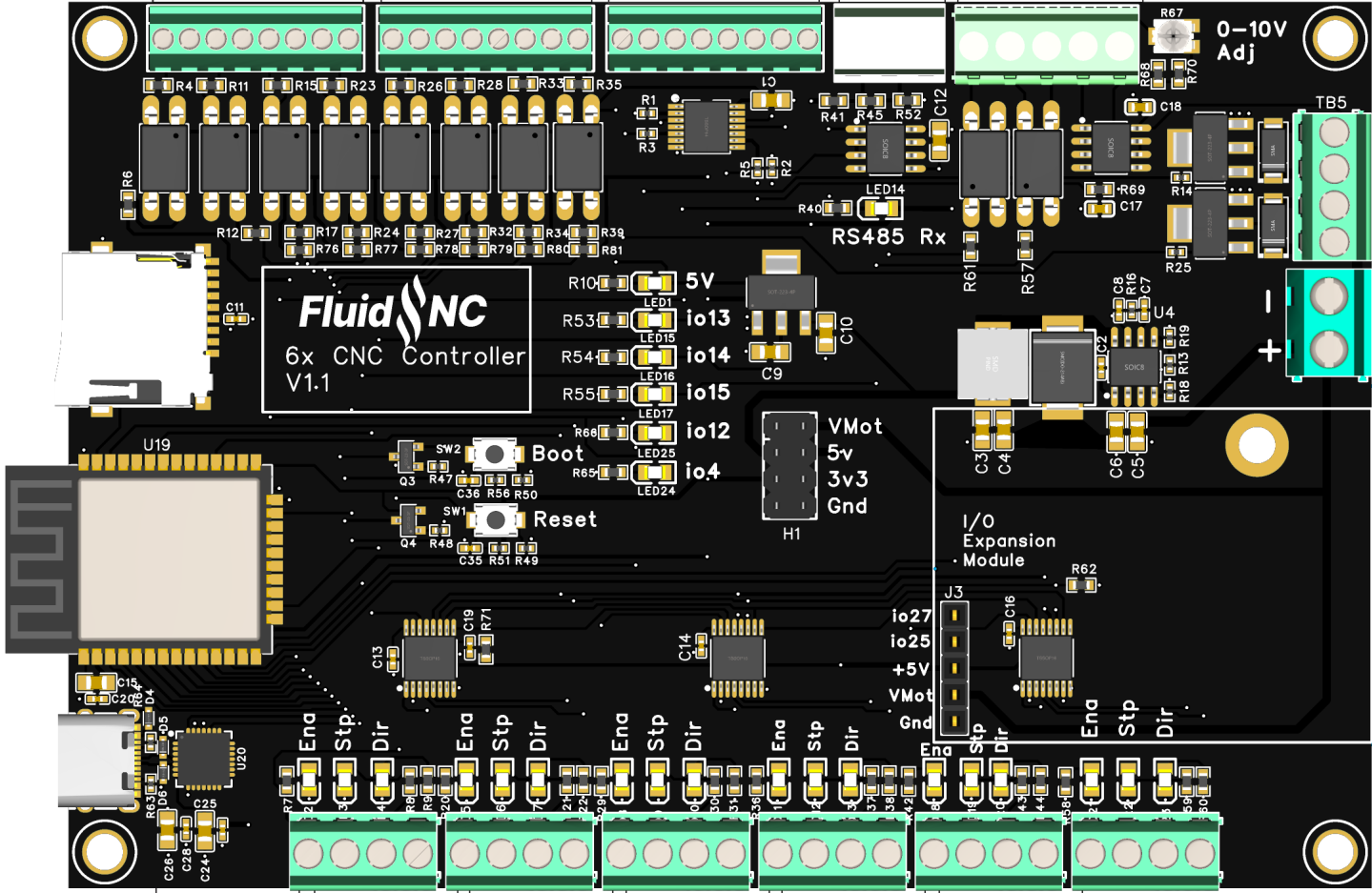
Pin Configuration and Descriptions
| Pin Number | Description | Notes |
|---|---|---|
| 1 | Spindle Enable | High to enable, low to disable |
| 2-9 | Axis Control (X, Y, Z) | Direction and step signals for each axis |
| 10 | Coolant Control | Activates coolant system |
| 11 | Emergency Stop | High signal triggers emergency shutdown |
| 12-13 | Reserved | For future use or custom functions |
| 14 | Spindle Speed Control | Analog signal for spindle speed regulation |
| 15-25 | Ground | Common ground for all signals |
Usage Instructions
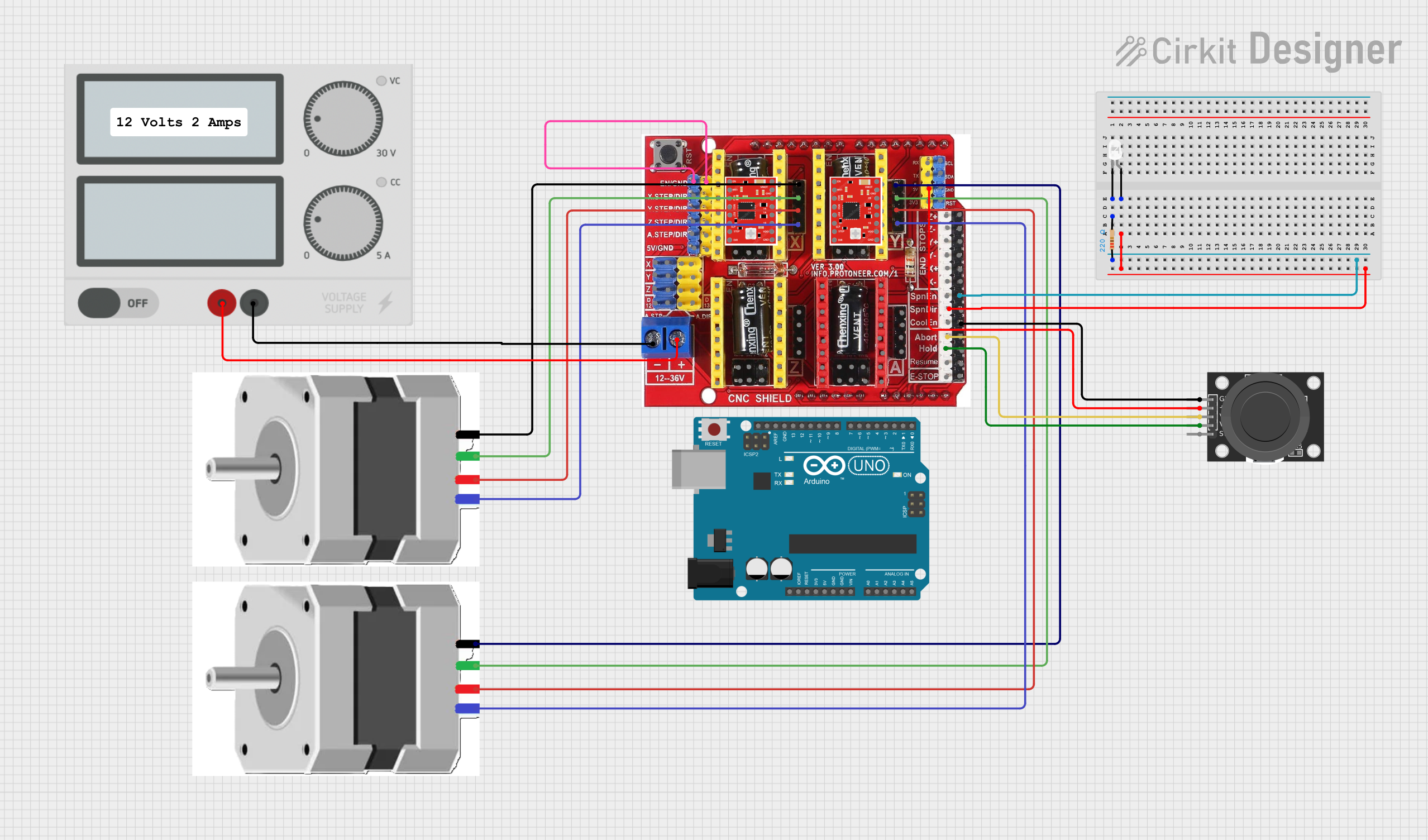
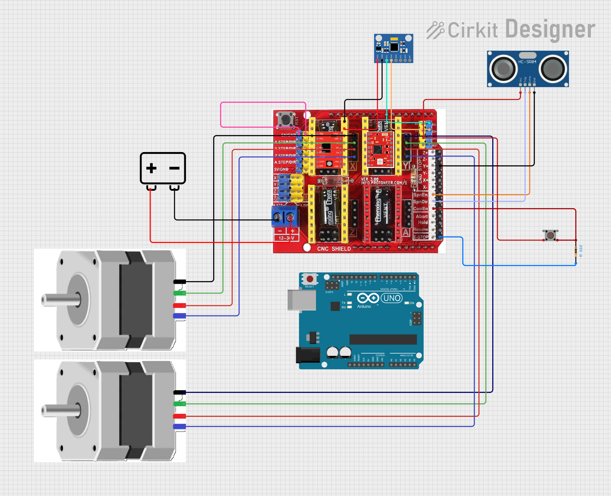
How to Use the 6xCNC in a Circuit
Power Supply Connection: Ensure that a stable 24V DC power supply is connected to the 6xCNC, capable of delivering sufficient current for the spindle and control electronics.
Control Interface: Connect the parallel port of the 6xCNC to a compatible CNC controller or computer interface capable of sending step and direction signals.
Tool Installation: Secure the desired cutting tool in the ER11 collet, ensuring it is tightly fastened to prevent slippage during operation.
Material Fixturing: Secure the material to be cut firmly to the machine bed to prevent movement during the cutting process.
Programming: Use CNC programming software to design the cutting path and generate the G-code necessary for the 6xCNC to execute the desired pattern or design.
Test Run: Perform a test run with the spindle turned off to verify the path and ensure there are no obstructions or errors in the programming.
Operation: Once verified, enable the spindle and start the cutting process, monitoring the operation for any anomalies.
Important Considerations and Best Practices
- Always wear safety glasses and follow safety protocols when operating the 6xCNC.
- Ensure proper ventilation and dust extraction to maintain a clean working environment.
- Regularly inspect and maintain the cutting tools and spindle for optimal performance.
- Use appropriate feed rates and cutting speeds for the material being machined to prevent tool wear and achieve the best finish.
Troubleshooting and FAQs
Common Issues
Q: The spindle does not start when enabled. A: Check the power supply and connections. Ensure the spindle enable pin is receiving a high signal.
Q: The cutting tool is not moving along the programmed path. A: Verify the axis control signals and ensure the G-code is correctly generated and transmitted.
Q: The finish on the cut material is poor or uneven. A: Inspect the cutting tool for wear or damage. Adjust the feed rate and spindle speed according to the material specifications.
Solutions and Tips for Troubleshooting
- If the 6xCNC is unresponsive, check all power and signal connections, and ensure the emergency stop is not engaged.
- For software-related issues, consult the CNC programming software's documentation and support resources.
- Regular calibration of the machine can prevent many accuracy-related problems.
Code Example for Arduino UNO
Below is an example of how to control the 6xCNC spindle using an Arduino UNO. This code assumes you have an appropriate interface circuit to convert the Arduino's signals to the required levels for the 6xCNC.
// Define pin connections
const int spindleEnablePin = 9; // PWM pin for spindle speed control

void setup() {
  // Set spindle pin as output
  pinMode(spindleEnablePin, OUTPUT);
  // Start with the spindle disabled
  analogWrite(spindleEnablePin, 0);
}

void loop() {
  // Enable spindle at half speed
  analogWrite(spindleEnablePin, 128); // 50% duty cycle for 0-10V control
  delay(10000); // Run spindle for 10 seconds
  // Disable spindle
  analogWrite(spindleEnablePin, 0);
  delay(5000); // Wait for 5 seconds
}
Note: The above code is a simple demonstration. In a real-world application, you would need to implement proper CNC control logic and safety checks. Always ensure that the Arduino and 6xCNC are electrically compatible and that any necessary level shifting or signal conditioning is in place.