How to Use BNO055: Examples, Pinouts, and Specs
Introduction
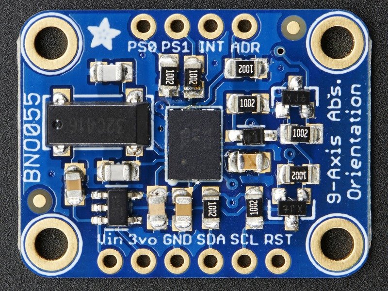
The BNO055 is a sophisticated 9-axis Absolute Orientation Sensor that combines a triaxial 16-bit gyroscope, a triaxial 14-bit accelerometer, and a triaxial geomagnetic sensor along with a 32-bit microcontroller running Bosch Sensortec sensor fusion software. This sensor is ideal for applications that require accurate orientation data such as robotics, augmented reality, gaming, personal navigation, and fitness tracking.
Explore Projects Built with BNO055
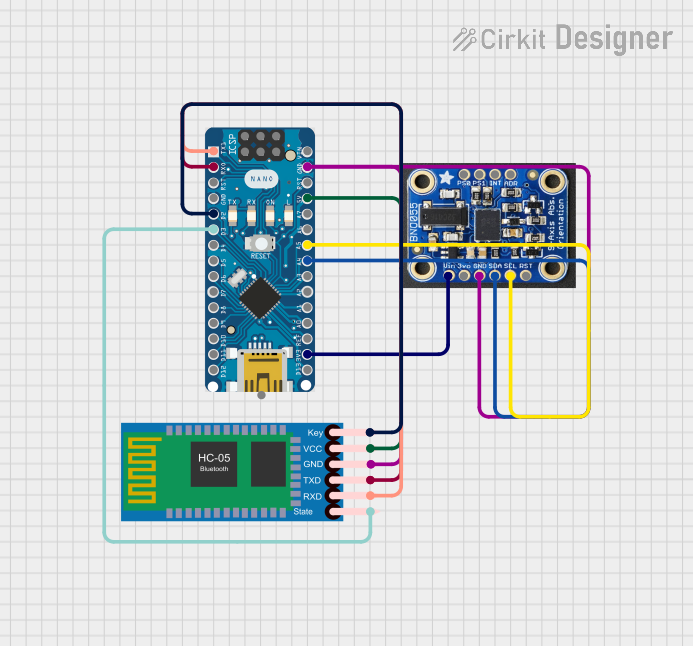
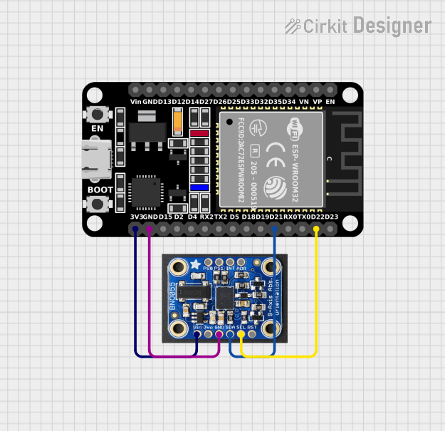

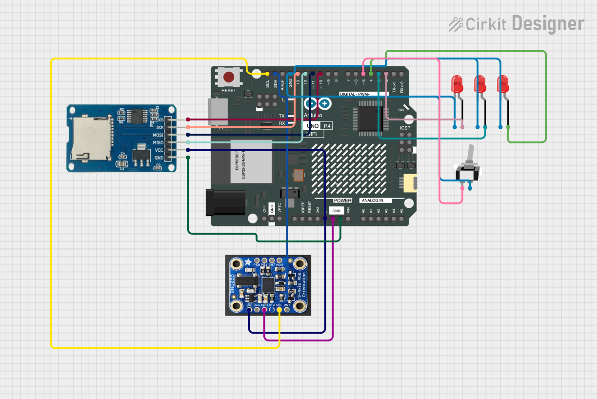
Explore Projects Built with BNO055
Common Applications and Use Cases
- Robotics: for balancing and navigational purposes.
- Virtual and Augmented Reality: for head tracking to provide immersive experiences.
- Wearable Devices: for activity recognition and step counting.
- Drones: for flight control and stabilization.
- Smartphones and Tablets: for screen orientation and motion detection.
Technical Specifications
Key Technical Details
- Operating Voltage: 3.3V to 5V
- Interface: I2C (up to 400kHz) and UART
- Operating Temperature Range: -40°C to +85°C
- Rotation Vector Output: 360°
- Heading Accuracy: 1°
- Angular Rate Resolution: 14 bits
Pin Configuration and Descriptions
| Pin Number | Pin Name | Description |
|---|---|---|
| 1 | VDD | Power supply (3.3V to 5V) |
| 2 | GND | Ground |
| 3 | SDA | Serial Data Line for I2C communication |
| 4 | SCL | Serial Clock Line for I2C communication |
| 5 | PS0/SDO | Protocol Select 0 / Serial Data Out |
| 6 | PS1 | Protocol Select 1 |
| 7 | INT | Interrupt output |
| 8 | ADR | I2C Address selection |
| 9 | RST | Reset input |
| 10 | BOOT | Bootloader access |
Usage Instructions
How to Use the BNO055 in a Circuit
- Powering the Sensor: Connect the VDD pin to a 3.3V or 5V power supply and the GND pin to the ground.
- I2C Communication: Connect the SDA and SCL pins to the corresponding SDA and SCL pins on your microcontroller (e.g., Arduino UNO).
- Address Selection: The ADR pin can be used to change the I2C address if multiple sensors are used on the same I2C bus.
- Interrupts: The INT pin can be connected to an external interrupt pin on your microcontroller to handle sensor events.
Important Considerations and Best Practices
- Ensure that the power supply is within the specified range to prevent damage.
- Use pull-up resistors on the I2C lines if they are not already present on your microcontroller board.
- When using multiple BNO055 sensors on the same I2C bus, make sure to set unique addresses for each sensor.
- For optimal performance, calibrate the sensor according to the manufacturer's instructions.
Example Code for Arduino UNO
#include <Wire.h>
#include <Adafruit_Sensor.h>
#include <Adafruit_BNO055.h>

// Check the I2C address in the datasheet and update if necessary
#define BNO055_ADDRESS (0x28)

Adafruit_BNO055 bno = Adafruit_BNO055(55, BNO055_ADDRESS);

void setup() {
  Serial.begin(9600);
  if (!bno.begin()) {
    Serial.println("No BNO055 detected. Check wiring or I2C address.");
    while (1);
  }
  bno.setExtCrystalUse(true);
}

void loop() {
  // Get orientation data
  imu::Vector<3> euler = bno.getVector(Adafruit_BNO055::VECTOR_EULER);

  // Output the orientation data
  Serial.print("X: ");
  Serial.print(euler.x());
  Serial.print(" Y: ");
  Serial.print(euler.y());
  Serial.print(" Z: ");
  Serial.println(euler.z());

  delay(100);
}
Troubleshooting and FAQs
Common Issues Users Might Face
- Sensor Not Detected: Ensure that the wiring is correct and the sensor is properly powered.
- Inaccurate Readings: Calibrate the sensor as per the datasheet instructions.
- I2C Communication Errors: Check for proper pull-up resistors and that the I2C address is correctly set.
Solutions and Tips for Troubleshooting
- Power Cycle the Sensor: Sometimes simply resetting the power can resolve issues.
- Check Solder Joints: Poor soldering can lead to intermittent connections.
- Use the Interrupt Pin: The INT pin can help manage sensor events and reduce the need for constant polling.
FAQs
Q: Can the BNO055 run on 5V systems? A: Yes, the BNO055 can operate on both 3.3V and 5V systems.
Q: How do I calibrate the BNO055? A: Follow the calibration procedure outlined in the datasheet, which typically involves moving the sensor through various positions.
Q: What is the default I2C address of the BNO055? A: The default I2C address is 0x28 (or 0x29 if the ADR pin is high).
Q: Can I use the BNO055 with an Arduino UNO? A: Yes, the BNO055 can be easily interfaced with an Arduino UNO using the I2C protocol.
This documentation provides a comprehensive guide to the BNO055 Absolute Orientation Sensor, ensuring users can effectively integrate and utilize this component in their projects.