How to Use 433mhz: Examples, Pinouts, and Specs
Introduction
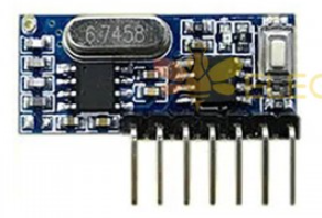
The 433MHz module is a wireless communication component that operates at a frequency of 433MHz. It is widely used in applications requiring low-power, long-range communication. This module is commonly found in remote controls, RFID systems, weather stations, home automation, and various IoT (Internet of Things) devices. Its simplicity, affordability, and effectiveness make it a popular choice for hobbyists and professionals alike.
Explore Projects Built with 433mhz


Explore Projects Built with 433mhz
Technical Specifications
The 433MHz module typically comes in two parts: a transmitter (TX) and a receiver (RX). Below are the key technical details for each:
Transmitter (TX) Specifications
- Operating Voltage: 3V - 12V DC (commonly 5V)
- Operating Current: ~10mA (at 5V)
- Frequency: 433.92MHz
- Transmission Range: Up to 100 meters (line of sight)
- Modulation Type: Amplitude Shift Keying (ASK)
- Data Rate: Up to 10kbps
Receiver (RX) Specifications
- Operating Voltage: 5V DC
- Operating Current: ~5mA
- Frequency: 433.92MHz
- Sensitivity: -105dBm
- Modulation Type: Amplitude Shift Keying (ASK)
- Data Rate: Up to 10kbps
Pin Configuration and Descriptions
Transmitter (TX) Pinout
| Pin Number | Pin Name | Description |
|---|---|---|
| 1 | VCC | Power supply (3V - 12V) |
| 2 | DATA | Data input for transmission |
| 3 | GND | Ground connection |
Receiver (RX) Pinout
| Pin Number | Pin Name | Description |
|---|---|---|
| 1 | GND | Ground connection |
| 2 | DATA | Data output (can have multiple pins) |
| 3 | VCC | Power supply (5V) |
| 4 | ANT | Antenna connection for better range |
Usage Instructions
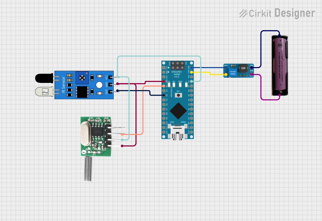
How to Use the 433MHz Module in a Circuit
Connect the Transmitter (TX):
- Connect the
VCCpin to a 5V power source. - Connect the
GNDpin to the ground of the circuit. - Connect the
DATApin to the microcontroller's digital output pin.
- Connect the
Connect the Receiver (RX):
- Connect the
VCCpin to a 5V power source. - Connect the
GNDpin to the ground of the circuit. - Connect the
DATApin to the microcontroller's digital input pin.
- Connect the
Antenna Setup:
- For both TX and RX, connect a simple wire (17.3 cm for 433MHz) to the
ANTpin to improve range and signal quality.
- For both TX and RX, connect a simple wire (17.3 cm for 433MHz) to the
Data Transmission:
- Use a microcontroller (e.g., Arduino UNO) to send and receive data. The transmitter sends digital signals, which the receiver decodes.
Important Considerations and Best Practices
- Ensure the transmitter and receiver are operating at the same frequency (433.92MHz).
- Use a proper antenna to maximize range and signal stability.
- Avoid interference by keeping the module away from other RF devices operating at similar frequencies.
- Use error-checking protocols in your code to ensure reliable data transmission.
Example Code for Arduino UNO
Below is an example of how to use the 433MHz module with an Arduino UNO for basic communication:
Transmitter Code
// Transmitter code for 433MHz module
#include <VirtualWire.h> // Include VirtualWire library for communication

void setup() {
  vw_setup(2000); // Set data rate to 2000 bits per second
  vw_set_tx_pin(12); // Set pin 12 as the transmitter pin
}

void loop() {
  const char *msg = "Hello, 433MHz!"; // Message to send
  vw_send((uint8_t *)msg, strlen(msg)); // Send the message
  vw_wait_tx(); // Wait for the transmission to complete
  delay(1000); // Wait 1 second before sending the next message
}
Receiver Code
// Receiver code for 433MHz module
#include <VirtualWire.h> // Include VirtualWire library for communication

void setup() {
  Serial.begin(9600); // Initialize serial communication
  vw_setup(2000); // Set data rate to 2000 bits per second
  vw_set_rx_pin(11); // Set pin 11 as the receiver pin
  vw_rx_start(); // Start the receiver
}

void loop() {
  uint8_t buf[VW_MAX_MESSAGE_LEN]; // Buffer to store received messages
  uint8_t buflen = VW_MAX_MESSAGE_LEN; // Length of the buffer

  if (vw_get_message(buf, &buflen)) { // Check if a message is received
    Serial.print("Received: ");
    for (int i = 0; i < buflen; i++) {
      Serial.print((char)buf[i]); // Print each character of the message
    }
    Serial.println();
  }
}
Troubleshooting and FAQs
Common Issues
No Signal Received:
- Ensure both TX and RX modules are powered correctly.
- Verify that the
DATApins are connected to the correct microcontroller pins. - Check the antenna connections for both modules.
Short Range:
- Use a proper antenna (17.3 cm wire for 433MHz).
- Ensure there are no physical obstructions or interference sources nearby.
Data Corruption:
- Use error-checking protocols in your code.
- Reduce the data rate if the environment is noisy.
FAQs
Q: Can I use the 433MHz module without an antenna?
A: While it is possible, the range and signal quality will be significantly reduced. An antenna is highly recommended.
Q: What is the maximum range of the 433MHz module?
A: The range can reach up to 100 meters in open space (line of sight) with a proper antenna.
Q: Can I use multiple 433MHz modules in the same area?
A: Yes, but you should implement unique identifiers or protocols to avoid interference between devices.
Q: Is the 433MHz module compatible with other frequencies?
A: No, the module is specifically designed to operate at 433.92MHz. Other frequencies require different modules.